S32 Design Studio PE工具配置GPIO
首先我们来讲最简单的GPIO配置
代码生成
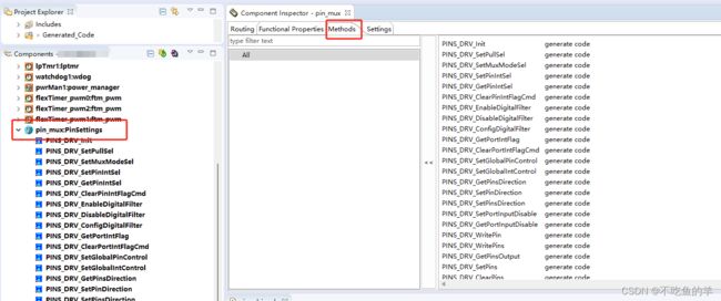
按照下图步骤就能配置一个基本的GPIO口,在组件里面选择pin_mux,选中就能配置使能和方向,no pin routed就是没有配置的。GPIO口分ABCDE组,每组从0到最大的序号。
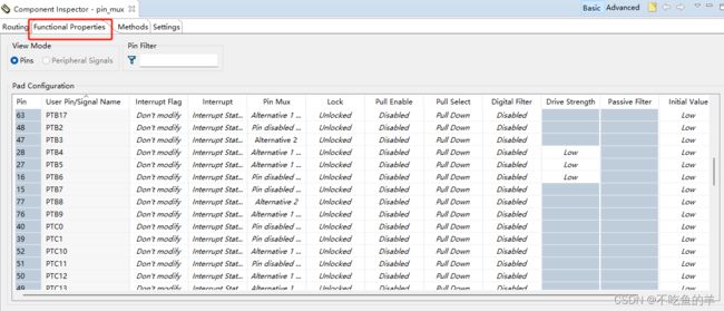
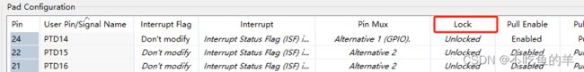
 然后在functional properties里面配置具体每一个引脚的复用、锁定、上拉下拉、数字过滤、输出初始值等等……
于是我们生成代码来看看,在文件pin_mux.c当中,会生成一个类型为pin_settings_config_t的g_pin_mux_InitConfigArr结构体数组。数组长度NUM_OF_CONFIGURED_PINS是GPIO口总数量,在pin_mux.h当中,也是会随着代码一起生成。
pin_settings_config_t g_pin_mux_InitConfigArr[NUM_OF_CONFIGURED_PINS] =
{
    ……
    {
        .base          = PORTB,
        .pinPortIdx    = 16u,
        .pullConfig    = PORT_INTERNAL_PULL_NOT_ENABLED,
        .passiveFilter = false,
        .driveSelect   = PORT_LOW_DRIVE_STRENGTH,
        .mux           = PORT_MUX_AS_GPIO,
        .pinLock       = false,
        .intConfig     = PORT_DMA_INT_DISABLED,
        .clearIntFlag  = false,
        .gpioBase      = PTB,
        .direction     = GPIO_OUTPUT_DIRECTION,
        .digitalFilter = false,
        .initValue     = 0u,
    },
    {
        .base          = PORTB,
        .pinPortIdx    = 15u,
        .pullConfig    = PORT_INTERNAL_PULL_NOT_ENABLED,
        .passiveFilter = false,
        .driveSelect   = PORT_LOW_DRIVE_STRENGTH,
        .mux           = PORT_MUX_ADC_INTERLEAVE,
        .pinLock       = false,
        .intConfig     = PORT_DMA_INT_DISABLED,
        .clearIntFlag  = false,
        .gpioBase      = PTB,
        .digitalFilter = false,
    }
    ……
}
配置对应
接下来我们一项一项看每一项配置是怎么对应代码的,base对应的是所在组的地址,gpioBase对应的是所在组的控制寄存器的地址。
PE自己对应的,使能就有,不用配置。
/** Peripheral PORTB base address */
#define PORTB_BASE                               (0x4004A000u)
/** Peripheral PORTB base pointer */
#define PORTB                                    ((PORT_Type *)PORTB_BASE)

/** Peripheral PTB base address */
#define PTB_BASE                                 (0x400FF040u)
/** Peripheral PTB base pointer */
#define PTB                                      ((GPIO_Type *)PTB_BASE)
pinPortIdx是该GPIO口在组内的序号
pullConfig有三个可选,上拉下拉和悬浮。
/*!
 * @brief Internal resistor pull feature selection
 * Implements : port_pull_config_t_Class
 */
typedef enum
{
    PORT_INTERNAL_PULL_NOT_ENABLED   = 0U,  /*!< internal pull-down or pull-up resistor is not enabled.           */
    PORT_INTERNAL_PULL_DOWN_ENABLED  = 1U,  /*!< internal pull-down resistor is enabled. @internal gui name="Down"*/
    PORT_INTERNAL_PULL_UP_ENABLED    = 2U   /*!< internal pull-up resistor is enabled. @internal gui name="Up"    */
} port_pull_config_t;
对应配置的pull select,不过要先将pull enable使能才行,不然就是默认的PORT_INTERNAL_PULL_NOT_ENABLED

passiveFilter被动滤波,一般不用,对应配置当中的Passive Filter

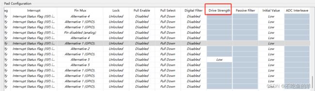
driveSelect驱动选择,就是上下拉的力量大小,电阻越小拉的电流越大。
/*!
 * @brief Configures the drive strength.
 * Implements : port_drive_strength_t_Class
 */
typedef enum
{
#if FEATURE_PINS_HAS_DRIVE_STRENGTH_CONTROL
    PORT_STRENGTH_DISABLED      = 0U, /*!< Output driver disabled                                         */
    PORT_LOW_DRIVE_STRENGTH     = 1U, /*!< Low drive strength is configured. Resistor is set to 240 Ohm   */
    PORT_STR1_DRIVE_STRENGTH    = 1U, /*!< Resistor is set to 240 Ohm                                     */
    PORT_STR2_DRIVE_STRENGTH    = 2U, /*!< Resistor is set to 240 / 2 Ohm = 120 Ohm                       */
    PORT_STR3_DRIVE_STRENGTH    = 3U, /*!< Resistor is set to 240 / 3 Ohm = 80 Ohm                        */
    PORT_STR4_DRIVE_STRENGTH    = 4U, /*!< Resistor is set to 240 / 4 Ohm = 60 Ohm                        */
    PORT_STR5_DRIVE_STRENGTH    = 5U, /*!< Resistor is set to 240 / 5 Ohm = 48 Ohm                        */
    PORT_STR6_DRIVE_STRENGTH    = 6U, /*!< Resistor is set to 240 / 6 Ohm = 40 Ohm                        */
    PORT_STR7_DRIVE_STRENGTH    = 7U, /*!< Resistor is set to 240 / 7 Ohm = 34 Ohm                        */
    PORT_HIGH_DRIVE_STRENGTH    = 7U  /*!< High drive strength is configured. Resistor is set to 240 Ohm  */
#else /* if not FEATURE_PINS_HAS_DRIVE_STRENGTH_CONTROL */
    PORT_LOW_DRIVE_STRENGTH     = 0U,    /*!< low drive strength is configured. @internal gui name="Low"  */
    PORT_HIGH_DRIVE_STRENGTH    = 1U     /*!< high drive strength is configured. @internal gui name="High"*/
#endif /* if FEATURE_PINS_HAS_DRIVE_STRENGTH_CONTROL */
} port_drive_strength_t;
对应配置Drive Strength,例子当中的这个芯片没那么多可以选的,只能选个low或者high。
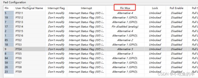
mux复用功能,一般都是PORT_MUX_AS_GPIO,ALT也就是alternative,如果复用ADC就是用PORT_MUX_ADC_INTERLEAVE。
/*!
 * @brief Configures the Pin mux selection
 * Implements : port_mux_t_Class
 */
typedef enum
{
    PORT_PIN_DISABLED            = 0U,  /*!< corresponding pin is disabled, but is used as an analog pin       */
    PORT_MUX_AS_GPIO             = 1U,  /*!< corresponding pin is configured as GPIO                           */
    PORT_MUX_ALT2                = 2U,  /*!< chip-specific                                                     */
    PORT_MUX_ALT3                = 3U,  /*!< chip-specific                                                     */
    PORT_MUX_ALT4                = 4U,  /*!< chip-specific                                                     */
    PORT_MUX_ALT5                = 5U,  /*!< chip-specific                                                     */
    PORT_MUX_ALT6                = 6U,  /*!< chip-specific                                                     */
    PORT_MUX_ALT7                = 7U,  /*!< chip-specific                                                     */
#if FEATURE_PINS_HAS_ADC_INTERLEAVE_EN
    PORT_MUX_ADC_INTERLEAVE      = 8U   /*!< when selected, ADC Interleaved channel is connected to current pin
                                         *   and disconnected to opposed pin
                                         * ADC1_SE14-PTB15 | ADC1_SE15-PTB16 | ADC0_SE8-PTC0  | ADC0_SE9-PTC1
                                         * ADC1_SE14-PTB0  | ADC1_SE15-PTB1  | ADC0_SE8-PTB13 | ADC0_SE9-PTB14 */
#endif /* FEATURE_PINS_HAS_ADC_INTERLEAVE_EN */
} port_mux_t;
对应配置的pin mux,普通IO口就是GPIO,模拟口就是analog。
pinLock对应lock,一般默认unlocked就行。
intConfig中断配置,要到对应的模块配置才行,不在GPIO口里面配置。
/*!
 * @brief Configures the interrupt generation condition.
 * Implements : port_interrupt_config_t_Class
 */
typedef enum
{
    PORT_DMA_INT_DISABLED  = 0x0U,  /*!< Interrupt/DMA request is disabled.                   */
    PORT_DMA_RISING_EDGE   = 0x1U,  /*!< DMA request on rising edge.                          */
    PORT_DMA_FALLING_EDGE  = 0x2U,  /*!< DMA request on falling edge.                         */
    PORT_DMA_EITHER_EDGE   = 0x3U,  /*!< DMA request on either edge.                          */
#if FEATURE_PORT_HAS_FLAG_SET_ONLY
    PORT_FLAG_RISING_EDGE  = 0x5U,  /*!< Flag sets on rising edge, no interrupt is generated. */
    PORT_FLAG_FALLING_EDGE = 0x6U,  /*!< Flag sets on falling edge, no interrupt is generated.*/
    PORT_FLAG_EITHER_EDGE  = 0x7U,  /*!< Flag sets on either edge, no interrupt is generated. */
#endif /* FEATURE_PORT_HAS_FLAG_SET_ONLY */
    PORT_INT_LOGIC_ZERO    = 0x8U,  /*!< Interrupt when logic 0.                              */
    PORT_INT_RISING_EDGE   = 0x9U,  /*!< Interrupt on rising edge.                            */
    PORT_INT_FALLING_EDGE  = 0xAU,  /*!< Interrupt on falling edge.                           */
    PORT_INT_EITHER_EDGE   = 0xBU,  /*!< Interrupt on either edge.                            */
    PORT_INT_LOGIC_ONE     = 0xCU,  /*!< Interrupt when logic 1.                              */
#if FEATURE_PORT_HAS_TRIGGER_OUT
    PORT_HIGH_TRIGGER_OUT  = 0xDU,  /*!< Enable active high trigger output, flag is disabled. */
    PORT_LOW_TRIGGER_OUT   = 0xEU   /*!< Enable active low trigger output, flag is disabled.  */
#endif /* FEATURE_PORT_HAS_TRIGGER_OUT */
} port_interrupt_config_t;
clearIntFlag和digitalFilter一般也是默认就行,对应interrupt flag和digital filter。

initValue是输出初始值,输入的IO口没有,只有输出的有,对应initial value。
![]()
接口函数
methods选项卡里面的接口函数跟展开pin_mux是一样的。生成的代码声明在pins_driver.h文件,函数原型在pins_driver.c文件,我们调用里面的接口就行。