芯片到uboot启动流程 :ROM → MLO(SPL)→ uboot.img
AM335x 中bootloader被分成了 3 个部分:
第一级 bootloader:引导加载程序,板子上电后会自动执行这些代码,如选择哪种方式启动(NAND,SDcard,UART。。。),然后跳转转到第二级 bootloader。这些代码应该是存放在 176KB 的 ROM 中。

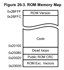
第二级 bootloader:MLO(SPL),用以硬件初始化:关闭看门狗,关闭中断,设置 CPU 时钟频率、速度等操作。然后会跳转到第三级bootloader。MLO文件应该会被映射到 64 KB的 Internal SRAM 中。

第三级 bootloader:uboot.img,C代码的入口。

其中第一级 bootloader 是板子固化的,第二级和第三级是通过编译 uboot 所得的。


2,第二级 bootloader:MLO(SPL)做了哪些事情?
MLO(SPL)内存分布如下:
SPL内存重映射:
|
1
2
3
4
5
6
7
8
9
10
11
12
13
14
15
16
17
18
19
20
21
22
23
24
25
26
27
28
29
30
31
32
33
34
35
36
|
< PATH :
/arch/arm/cpu/armv7/omap-common/u-boot-spl
.lds >
MEMORY { .sram : ORIGIN = CONFIG_SPL_TEXT_BASE,\
LENGTH = CONFIG_SPL_MAX_SIZE }
MEMORY { .sdram : ORIGIN = CONFIG_SPL_BSS_START_ADDR, \
LENGTH = CONFIG_SPL_BSS_MAX_SIZE }
OUTPUT_FORMAT(
"elf32-littlearm"
,
"elf32-littlearm"
,
"elf32-littlearm"
)
OUTPUT_ARCH(arm)
ENTRY(_start)
SECTIONS
{
.text :
{
__start = .;
arch
/arm/cpu/armv7/start
.o (.text)
*(.text*)
} >.sram
. = ALIGN(4);
.rodata : { *(SORT_BY_ALIGNMENT(.rodata*)) } >.sram
. = ALIGN(4);
.data : { *(SORT_BY_ALIGNMENT(.data*)) } >.sram
. = ALIGN(4);
__image_copy_end = .;
_end = .;
.bss :
{
. = ALIGN(4);
__bss_start = .;
*(.bss*)
. = ALIGN(4);
__bss_end__ = .;
} >.sdram
}
|
|
1
2
3
4
5
6
7
|
#define CONFIG_SPL_TEXT_BASE 0x402F0400
#define CONFIG_SPL_MAX_SIZE (46 * 1024)
#define CONFIG_SPL_STACK LOW_LEVEL_SRAM_STACK
#define CONFIG_SPL_BSS_START_ADDR 0x80000000
#define CONFIG_SPL_BSS_MAX_SIZE 0x80000 /* 512 KB */
|
@1@ 保存启动参数 bl save_boot_params
|
1
2
3
4
5
6
7
|
/*
* the actual reset code
*/
reset:
bl save_boot_params
|
|
1
2
3
4
5
6
7
8
9
10
11
12
13
14
15
16
17
18
19
20
21
22
23
24
|
.global save_boot_params
save_boot_params:
/*
* See
if
the rom code passed pointer is valid:
* It is not valid
if
it is not
in
non-secure SRAM
* This may happen
if
you are booting with the help of
* debugger
*/
ldr r2, =NON_SECURE_SRAM_START
cmp
r2, r0
bgt 1f
ldr r2, =NON_SECURE_SRAM_END
cmp
r2, r0
blt 1f
/*
* store the boot params passed from rom code or saved
* and passed by SPL
*/
cmp
r0,
#0
beq 1f
ldr r1, =boot_params
str r0, [r1]
|
|
1
2
3
4
5
6
7
8
|
/*《PATH: /arch/arm/include/asm/arch-ti81xx/omap.h》
* Non-secure SRAM Addresses
* Non-secure RAM starts at 0x40300000 for GP devices. But we keep SRAM_BASE
* at 0x40304000(EMU base) so that our code works for both EMU and GP
*/
#define NON_SECURE_SRAM_START 0x40304000
#define NON_SECURE_SRAM_END 0x4030E000
#define LOW_LEVEL_SRAM_STACK 0x4030B7FC
|
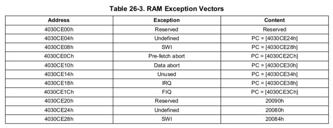
问题:这些参数是保存在哪里的?大概有哪些参数?
答:
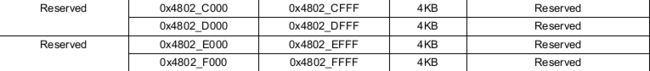
这些参数保存的内存地址为 64 KB 的 OCM RAM 中:


注:Dowloaded Image 区域:是用来保存 MLO(SPL) 文件的,其最大可达到 109 KB


@a2@ 设置 CPU 为 SVC32 模式
|
1
2
3
4
5
6
7
8
|
/*
*
set
the cpu to SVC32 mode
*/
mrs r0, cpsr
bic r0, r0,
#0x1f
orr r0, r0,
#0xd3
msr cpsr,r0
|
CPSR:程序状态寄存器(current program status register) (当前程序状态寄存器),在任何处理器模式下被访问。它包含了条件标志位、中断禁止位、当前处理器模式标志以及其他的一些控制和状态位。
CPSR在用户级编程时用于存储条件码。
SPSR:程序状态保存寄存器(saved program status register),每一种处理器模式下都有一个状态寄存器SPSR,SPSR用于保存CPSR的状态,以便异常返回后恢复异常发生时的工作状态。当特定 的异常中断发生时,这个寄存器用于存放当前程序状态寄存器的内容。在异常中断退出时,可以用SPSR来恢复CPSR。由于用户模式和系统模式不是异常中断 模式,所以他没有SPSR。当用户在用户模式或系统模式访问SPSR,将产生不可预知的后果。
CPSR格式如下所示。SPSR和CPSR格式相同。
31 30 29 28 27 26 7 6 5 4 3 2 1 0
N Z C V Q DNM(RAZ) I F T M4 M3 M2 M1 M0
详解:http://blog.chinaunix.net/uid-28458801-id-3487199.html
@a3@ CPU的初始化
|
1
2
3
4
5
|
《PATH : /arch/arm/cpu/armv7/start.S》
/* the mask ROM code should have PLL and others stable */
#ifndef CONFIG_SKIP_LOWLEVEL_INIT
bl cpu_init_crit
#endif
|
|
1
2
3
4
5
6
7
8
9
10
11
12
13
14
15
16
17
18
|
.globl lowlevel_init
lowlevel_init:
/*
* Setup a temporary stack
*/
ldr sp, =LOW_LEVEL_SRAM_STACK
/*
* Save the old lr(passed
in
ip) and the current lr to stack
*/
push {ip, lr}
/*
* go setup pll, mux, memory
*/
bl s_init
pop {ip, pc}
|
问题:CPU的初始化有哪些内容?
答:
@b1@ 首先要设置堆栈区,因为将会调用 C函数来实现CPU的初始化
问题:这个堆栈在什么位置,其内存大小是多少?
答
|
1
2
|
《PATH :/arch/arm/
include
/asm/arch-ti81xx/omap.h》
#define LOW_LEVEL_SRAM_STACK
0x4030B7FC
|


@b2@ 执行 s_init() 函数,实现 CPU 的初始化
|
1
2
3
4
5
6
7
8
9
10
11
12
13
14
15
16
17
18
19
20
21
22
23
24
25
26
27
28
29
30
31
32
33
34
35
36
37
38
39
40
41
42
43
44
45
46
47
48
49
50
51
52
53
54
55
56
57
58
59
60
|
/*
* early system init of muxing and clocks.
*/
void
s_init(
void
)
{
/* Can be removed as A8 comes up with L2 enabled */
l2_cache_enable();
/* WDT1 is already running when the bootloader gets control
* Disable it to avoid "random" resets
*/
__raw_writel(
0xAAAA
, WDT_WSPR);
while
(__raw_readl(WDT_WWPS) !=
0x0
);
__raw_writel(
0x5555
, WDT_WSPR);
while
(__raw_readl(WDT_WWPS) !=
0x0
);
#ifdef CONFIG_SPL_BUILD
/* Setup the PLLs and the clocks for the peripherals */
pll_init();
/* Enable RTC32K clock */
rtc32k_enable();
/* UART softreset */
u32 regVal;
u32 uart_base = DEFAULT_UART_BASE;
enable_uart0_pin_mux();
/* IA Motor Control Board has default console on UART3*/
/* XXX: This is before we've probed / set board_id */
if
(board_id == IA_BOARD) {
uart_base = UART3_BASE;
}
regVal = __raw_readl(uart_base + UART_SYSCFG_OFFSET);
regVal |= UART_RESET;
__raw_writel(regVal, (uart_base + UART_SYSCFG_OFFSET) );
while
((__raw_readl(uart_base + UART_SYSSTS_OFFSET) &
UART_CLK_RUNNING_MASK) != UART_CLK_RUNNING_MASK);
/* Disable smart idle */
regVal = __raw_readl((uart_base + UART_SYSCFG_OFFSET));
regVal |= UART_SMART_IDLE_EN;
__raw_writel(regVal, (uart_base + UART_SYSCFG_OFFSET));
/* Initialize the Timer */
init_timer();
preloader_console_init();
printf(
"\nlocation /board/ti/am335x\n"
);
//@@
/*@@*/
// led();
/*@@*/
config_am335x_ddr();
#endif
}
|
@c1@ 使能第二级缓冲区
|
1
2
3
4
5
6
7
8
9
10
|
/* Can be removed as A8 comes up with L2 enabled */
l2_cache_enable();
l2_cache_enable:
push {r0, r1, r2, lr}
mrc 15, 0, r3, cr1, cr0, 1
orr r3, r3, #2
mcr 15, 0, r3, cr1, cr0, 1
pop {r1, r2, r3, pc}
|

@c2@ 关闭看门狗(WDT)
|
1
2
3
4
5
6
7
|
/* WDT1 is already running when the bootloader gets control
* Disable it to avoid "random" resets
*/
__raw_writel(0xAAAA, WDT_WSPR);
while
(__raw_readl(WDT_WWPS) != 0x0);
__raw_writel(0x5555, WDT_WSPR);
while
(__raw_readl(WDT_WWPS) != 0x0);
|
|
1
2
3
4
5
6
7
8
9
10
11
|
#define WDT_WSPR (WDT_BASE +
0x048
)
/* Watchdog Timer */
#ifdef CONFIG_AM335X
#define WDT_BASE
0x44E35000
#
else
#define WDT_BASE
0x480C2000
#endif
|


@c3@ 给外设设置好 PLL 和 时钟频率等
|
1
2
3
4
5
6
7
8
9
10
11
12
13
14
15
16
17
18
19
20
21
|
/* Setup the PLLs and the clocks for the peripherals */
pll_init();
/*
* Configure the PLL/PRCM for necessary peripherals
*/
void
pll_init()
{
mpu_pll_config(MPUPLL_M_500);
core_pll_config();
per_pll_config();
ddr_pll_config();
/* Enable the required interconnect clocks */
interface_clocks_enable();
/* Enable power domain transition */
power_domain_transition_enable();
/* Enable the required peripherals */
per_clocks_enable();
}
|
@c4@ 使能 32-KHz 频率的实时时钟
|
1
2
3
4
5
6
7
8
9
10
11
12
13
14
15
16
17
18
19
20
21
22
23
|
/* Enable RTC32K clock */
rtc32k_enable();
《PATH : /board/ti/am335x/evm.c》
static
void
rtc32k_enable(
void
)
{
/* Unlock the rtc's registers */
__raw_writel(
0x83e70b13
, (AM335X_RTC_BASE + RTC_KICK0_REG));
__raw_writel(
0x95a4f1e0
, (AM335X_RTC_BASE + RTC_KICK1_REG));
/* Enable the RTC 32K OSC */
__raw_writel(
0x48
, (AM335X_RTC_BASE + RTC_OSC_REG));
}
/* RTC base address */
#define AM335X_RTC_BASE
0x44E3E000
#define RTC_KICK0_REG
0x6c
#define RTC_KICK1_REG
0x70
#define RTC_OSC_REG
0x54
|

@c5@ 使能UART0
|
1
2
3
4
5
6
7
8
9
10
11
12
13
14
15
16
17
18
19
20
21
22
23
24
25
26
27
28
29
30
31
32
33
34
|
/* UART softreset */
u32 regVal;
u32 uart_base = DEFAULT_UART_BASE;
enable_uart0_pin_mux();
/* IA Motor Control Board has default console on UART3*/
/* XXX: This is before we've probed / set board_id */
if
(board_id == IA_BOARD) {
uart_base = UART3_BASE;
}
regVal = __raw_readl(uart_base + UART_SYSCFG_OFFSET);
regVal |= UART_RESET;
__raw_writel(regVal, (uart_base + UART_SYSCFG_OFFSET) );
while
((__raw_readl(uart_base + UART_SYSSTS_OFFSET) &
UART_CLK_RUNNING_MASK) != UART_CLK_RUNNING_MASK);
/* Disable smart idle */
regVal = __raw_readl((uart_base + UART_SYSCFG_OFFSET));
regVal |= UART_SMART_IDLE_EN;
__raw_writel(regVal, (uart_base + UART_SYSCFG_OFFSET));
#ifdef CONFIG_AM335X
#define DEFAULT_UART_BASE UART0_BASE
#endif
#ifdef CONFIG_AM335X
#define UART0_BASE 0x44E09000
#else
#define UART0_BASE 0x48020000
#endif
|

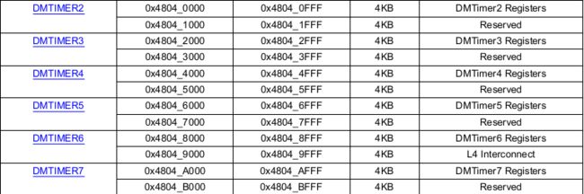
@c6@ 初始化 定时器
|
1
2
3
4
5
6
7
8
9
10
11
12
13
14
15
16
17
18
19
20
21
22
23
24
25
26
27
|
/* Initialize the Timer */
init_timer();
static
void
init_timer(
void
)
{
/* Reset the Timer */
__raw_writel(
0x2
, (DM_TIMER2_BASE + TSICR_REG));
/* Wait until the reset is done */
while
(__raw_readl(DM_TIMER2_BASE + TIOCP_CFG_REG) &
1
);
/* Start the Timer */
__raw_writel(
0x1
, (DM_TIMER2_BASE + TCLR_REG));
}
/* DM Timer base addresses */
#define DM_TIMER0_BASE
0x4802C000
#define DM_TIMER1_BASE
0x4802E000
#define DM_TIMER2_BASE
0x48040000
#define DM_TIMER3_BASE
0x48042000
#define DM_TIMER4_BASE
0x48044000
#define DM_TIMER5_BASE
0x48046000
#define DM_TIMER6_BASE
0x48048000
#define DM_TIMER7_BASE
0x4804A000
|
@c7@ 初始化控制台,通过UART可以查看相关信息
|
1
2
3
4
5
6
7
8
9
10
11
12
13
14
15
16
17
18
19
20
21
22
23
24
|
preloader_console_init();
《PATH : /arch/arm/cpu/armv7/omap-common/spl.c》
/* This requires UART clocks to be enabled */
void
preloader_console_init(
void
)
{
const
char
*u_boot_rev = U_BOOT_VERSION;
char
rev_string_buffer[50];
gd = &gdata;
gd->bd = &bdata;
gd->flags |= GD_FLG_RELOC;
gd->baudrate = CONFIG_BAUDRATE;
serial_init();
/* serial communications setup */
/* Avoid a second "U-Boot" coming from this string */
u_boot_rev = &u_boot_rev[7];
printf
(
"\nU-Boot SPL %s (%s - %s)\n"
, u_boot_rev, U_BOOT_DATE,
U_BOOT_TIME);
omap_rev_string(rev_string_buffer);
printf
(
"Texas Instruments %s\n"
, rev_string_buffer);
}
|
@c8@ 配置 DDR
|
1
2
3
4
5
6
7
8
9
10
11
12
13
14
15
16
17
18
19
20
21
22
23
24
25
26
27
28
29
30
31
32
33
34
35
36
37
38
39
40
41
42
43
|
config_am335x_ddr();
《PATH :》
/* void DDR2_EMIF_Config(void); */
static
void
config_am335x_ddr(
void
)
{
int
data_macro_0 = 0;
int
data_macro_1 = 1;
enable_ddr_clocks();
config_vtp();
Cmd_Macro_Config();
Data_Macro_Config(data_macro_0);
Data_Macro_Config(data_macro_1);
__raw_writel(PHY_RANK0_DELAY, DATA0_RANK0_DELAYS_0);
__raw_writel(PHY_RANK0_DELAY, DATA1_RANK0_DELAYS_0);
__raw_writel(DDR_IOCTRL_VALUE, DDR_CMD0_IOCTRL);
__raw_writel(DDR_IOCTRL_VALUE, DDR_CMD1_IOCTRL);
__raw_writel(DDR_IOCTRL_VALUE, DDR_CMD2_IOCTRL);
__raw_writel(DDR_IOCTRL_VALUE, DDR_DATA0_IOCTRL);
__raw_writel(DDR_IOCTRL_VALUE, DDR_DATA1_IOCTRL);
__raw_writel(__raw_readl(DDR_IO_CTRL) & 0xefffffff, DDR_IO_CTRL);
__raw_writel(__raw_readl(DDR_CKE_CTRL) | 0x00000001, DDR_CKE_CTRL);
config_emif_ddr2();
}
《PATH : /arm/include/asm/arch-ti81xx/cpu.h》
#define DATA0_RANK0_DELAYS_0 (DDR_PHY_BASE_ADDR + 0x134)
#define DATA1_RANK0_DELAYS_0 (DDR_PHY_BASE_ADDR + 0x1D8)
/* DDR offsets */
#define DDR_PHY_BASE_ADDR 0x44E12000
#define DDR_IO_CTRL 0x44E10E04
#define DDR_CKE_CTRL 0x44E1131C
|