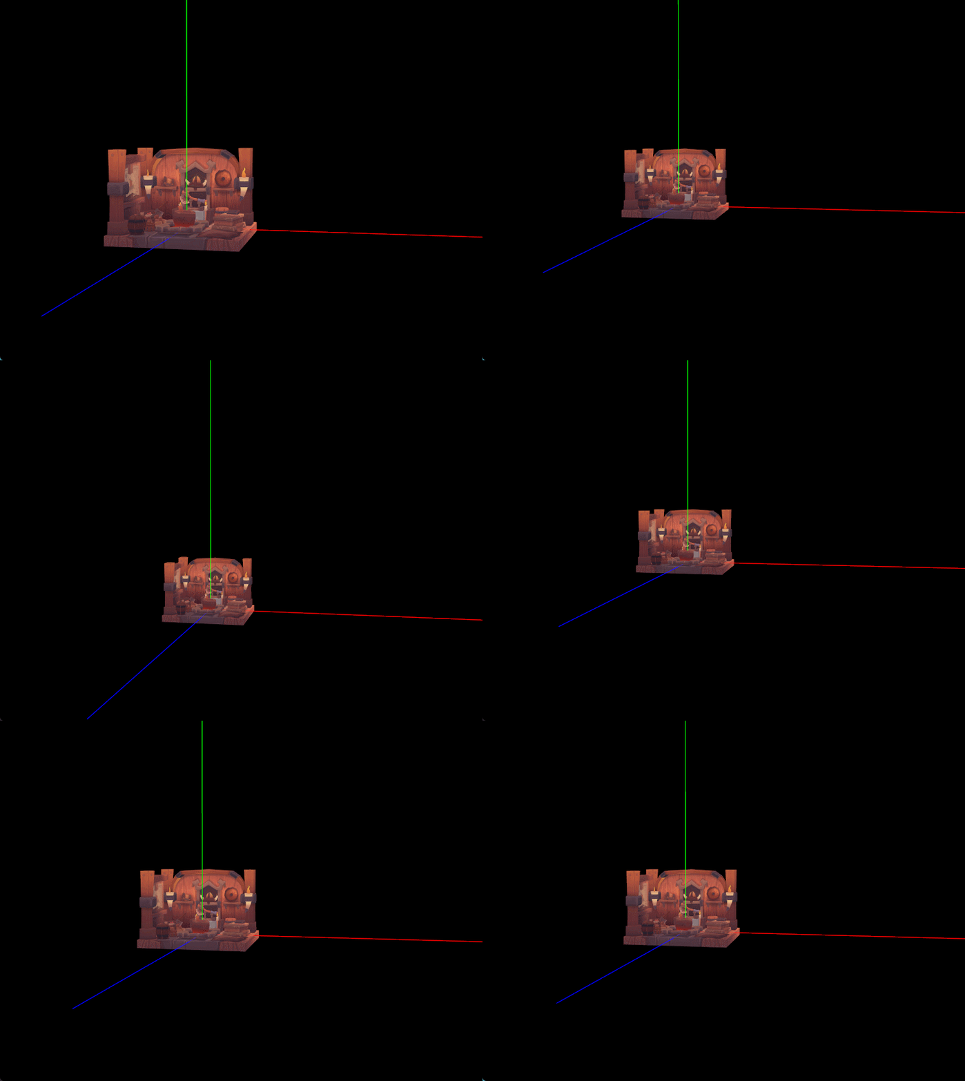
Vulkan多管线渲染与绘制世界坐标轴Axis
一、多管线渲染
设置 vulkan 图形管线要点
vulkan API 绘制不同的拓扑类型,比如三角形、线段、点都要重新设置图形管线。可以在初始化过程中设置多套不同的管线缓存起来,然后在绘制帧的时候绑定需要的管线进行绘制,这比每次绘制的时候重新创建管线性能要好得多。如果缓存了很多管线,每次绘制一个模型实例就绑定一次某个管线,那么性能也会不好。绘制的时候应该根据不同类型的管线对模型实例进行分组绘制,每绑定一种图形管线,就把那种图形管线对应的模型实例都放到一个集合中进行批量绘制,这样总体下来性能影响可以忽略不计。
在vkinit 中创建两套管线分别用于绘制线段和三角形
- 多个渲染管线(VkPipeline)完全可以复用同一个管线布局(VkPipelineLayout),只要它们的 descriptor set layout 和 push constant 定义一致即可,这样可以减少资源和管理复杂度,也方便切换管线。常见做法就是:
- 用同一套 descriptor set layout 和 push constant 定义,创建一个 VkPipelineLayout。
- 所有相关的管线(如三角形管线、线管线、不同着色器管线)都用这个 pipeline layout。
- 不同的管线绑定不同的着色器。画线的绑定线段专用着色器,片段着色器中移除纹理采样可以提供性能;画三角形的继续使用之前带纹理采样的片段着色器。
 // 创建图形管线
 {
       VkPushConstantRange pushConstantRange{};
       pushConstantRange.stageFlags = VK_SHADER_STAGE_VERTEX_BIT;
       pushConstantRange.offset = 0;
       pushConstantRange.size = sizeof(PushConstants);

       VkPipelineLayoutCreateInfo pipelineLayoutInfo{};
       pipelineLayoutInfo.sType = VK_STRUCTURE_TYPE_PIPELINE_LAYOUT_CREATE_INFO;
       pipelineLayoutInfo.setLayoutCount = 1;
       pipelineLayoutInfo.pSetLayouts = &ctx->descriptorSetLayout;
       pipelineLayoutInfo.pushConstantRangeCount = 1;
       pipelineLayoutInfo.pPushConstantRanges = &pushConstantRange;

       if (vkCreatePipelineLayout(ctx->device, &pipelineLayoutInfo, nullptr, &ctx->pipelineLayout) != VK_SUCCESS) {
           throw std::runtime_error("创建管线布局失败!");
       }

       // 绘制线段的管线
       ctx->piplelineLine = createPipeline(ctx,
           VK_PRIMITIVE_TOPOLOGY_LINE_LIST,
           "assets/shaders/line.vert.spv",
           "assets/shaders/line.frag.spv");

       // 绘制三角形的管线
       ctx->piplelineTriangle = createPipeline(ctx,
           VK_PRIMITIVE_TOPOLOGY_TRIANGLE_LIST,
           "assets/shaders/triangle.vert.spv",
           "assets/shaders/triangle.frag.spv");
   }
模型按类型实例分组
在 VkContext 结构中添加 std::vector属性用于存放线段类型的网格对象,原来的std::vector存储三角形类型的网格对象。
- 更新 main.cpp
...
axis = new Axis();
vkcontext.lineInstances.push_back(axis);

MeshInstance* objModel = ObjModelLoader::loadModel("assets/models/viking_room.obj", "assets/models/viking_room.png");
vkcontext.meshInstances.push_back(objModel);
...
分别为lineInstances和meshInstances创建顶点/索引缓冲
// 创建顶点缓冲
 for (MeshInstance* mesh : ctx->lineInstances) {
     if (mesh->vertices.empty()) continue;
     createVertexBuffer(mesh, ctx);
 }
 for (MeshInstance* mesh : ctx->meshInstances) {
     if (mesh->vertices.empty()) continue;
     createVertexBuffer(mesh, ctx);
 }

 // 创建索引缓冲
 for (MeshInstance* mesh : ctx->lineInstances) {
     if (mesh->indices.empty()) continue;
     createIndexBuffer(mesh, ctx);
 }
 for (MeshInstance* mesh : ctx->meshInstances) {
     if (mesh->indices.empty()) continue;
     createIndexBuffer(mesh, ctx);
 }
更新描述符池代码
  // 创建描述符池
  {
         std::array<VkDescriptorPoolSize, 2> poolSizes{};
         size_t meshCount = ctx->meshInstances.size() + ctx->lineInstances.size(); // 所有网格实例数量总和
         poolSizes[0].type = VK_DESCRIPTOR_TYPE_UNIFORM_BUFFER;
         poolSizes[0].descriptorCount = static_cast<uint32_t>(MAX_CONCURRENT_FRAMES * meshCount) + 1;
         poolSizes[1].type = VK_DESCRIPTOR_TYPE_COMBINED_IMAGE_SAMPLER;
         poolSizes[1].descriptorCount = static_cast<uint32_t>(MAX_CONCURRENT_FRAMES * meshCount) + 1;

         VkDescriptorPoolCreateInfo poolInfo{};
         poolInfo.sType = VK_STRUCTURE_TYPE_DESCRIPTOR_POOL_CREATE_INFO;
         poolInfo.poolSizeCount = static_cast<uint32_t>(poolSizes.size());
         poolInfo.pPoolSizes = poolSizes.data();
         poolInfo.maxSets = static_cast<uint32_t>(MAX_CONCURRENT_FRAMES * meshCount) + 1;
         poolInfo.flags = VK_DESCRIPTOR_POOL_CREATE_FREE_DESCRIPTOR_SET_BIT;

         if (vkCreateDescriptorPool(ctx->device, &poolInfo, nullptr, &ctx->descriptorPool) != VK_SUCCESS) {
             throw std::runtime_error("创建描述符池失败!");
         }
     }
更新描述符集代码
   // 创建描述符集
   {
        std::vector<VkDescriptorSetLayout> layouts(MAX_CONCURRENT_FRAMES, ctx->descriptorSetLayout);
        size_t modelCount = ctx->lineInstances.size() + ctx->meshInstances.size();
        ctx->descriptorSets.resize(modelCount);

		// 分别为不同的实例集合创建描述符集
        createDescriptorSets(layouts, ctx->lineInstances, 0, ctx);
        createDescriptorSets(layouts, ctx->meshInstances, ctx->lineInstances.size(), ctx);
    }
分组绑定管线和绘制
- 更新记录缓冲区代码:
/**
 * 录制用于渲染一帧的命令缓冲区
 *
 * @param commandBuffer 要录制的命令缓冲区
 * @param imageIndex 当前交换链图像的索引
 * @param imguiDrawData ImGui 绘制数据
 * @param ctx Vulkan 上下文结构,包含必要的 Vulkan 对象
 */
void recordCommandBuffer(VkCommandBuffer commandBuffer,
                         uint32_t imageIndex,
                         ImDrawData* imguiDrawData,
                         VkContext* ctx) {
    // 开始命令缓冲区录制
    VkCommandBufferBeginInfo beginInfo{};
    beginInfo.sType = VK_STRUCTURE_TYPE_COMMAND_BUFFER_BEGIN_INFO;

    if (vkBeginCommandBuffer(commandBuffer, &beginInfo) != VK_SUCCESS) {
        throw std::runtime_error("录制命令缓冲失败!");
    }

    // 设置渲染通道信息
    VkRenderPassBeginInfo renderPassInfo{};
    renderPassInfo.sType = VK_STRUCTURE_TYPE_RENDER_PASS_BEGIN_INFO;
    renderPassInfo.renderPass = ctx->renderPass;
    renderPassInfo.framebuffer = ctx->swapChainFramebuffers[imageIndex];
    renderPassInfo.renderArea.offset = {0, 0};
    renderPassInfo.renderArea.extent = ctx->swapChainExtent;

    // 设置清除值:颜色缓冲区为黑色,深度缓冲区为1.0
    std::array<VkClearValue, 2> clearValues{};
    clearValues[0].color = {{0.0f, 0.0f, 0.0f, 1.0f}};
    clearValues[1].depthStencil = {1.0f, 0};
    renderPassInfo.clearValueCount = static_cast<uint32_t>(clearValues.size());
    renderPassInfo.pClearValues = clearValues.data();

    // 开始渲染通道
    vkCmdBeginRenderPass(commandBuffer, &renderPassInfo, VK_SUBPASS_CONTENTS_INLINE);

    // 绑定线条渲染管线并设置视口和裁剪
    vkCmdBindPipeline(commandBuffer, VK_PIPELINE_BIND_POINT_GRAPHICS, ctx->piplelineLine);
    setViewportAndScissor(commandBuffer, ctx);

    // 计算投影和视图矩阵
    float aspectRatio = ctx->swapChainExtent.width / (float) ctx->swapChainExtent.height;
    glm::mat4 projMatrix = ctx->camera->getProjectionMatrix(aspectRatio);
    glm::mat4 viewMatrix = ctx->camera->getViewMatrix();

    // 渲染所有线网格实例
    size_t meshIndex = 0;
    for (; meshIndex < ctx->lineInstances.size(); ++meshIndex) {
        auto* mesh = ctx->lineInstances[meshIndex];
        // 计算模型-视图-投影矩阵并通过PushConstants传递给着色器
        PushConstants pc{};
        pc.mvp = projMatrix * viewMatrix * mesh->modelMatrix;
        vkCmdPushConstants(
            commandBuffer, ctx->pipelineLayout, VK_SHADER_STAGE_VERTEX_BIT, 0, sizeof(PushConstants), &pc);

        // 绑定顶点和索引缓冲区
        VkDeviceSize offsets[] = {0};
        vkCmdBindVertexBuffers(commandBuffer, 0, 1, &mesh->vertexBuffer, offsets);
        vkCmdBindIndexBuffer(commandBuffer, mesh->indexBuffer, 0, VK_INDEX_TYPE_UINT32);

        // 绑定描述符集并绘制
        vkCmdBindDescriptorSets(commandBuffer,
                                VK_PIPELINE_BIND_POINT_GRAPHICS,
                                ctx->pipelineLayout,
                                0,
                                1,
                                &ctx->descriptorSets[meshIndex][ctx->currentFrame],
                                0,
                                nullptr);
        vkCmdDrawIndexed(commandBuffer, mesh->indices.size(), 1, 0, 0, 0);
    }

    // 绑定三角形渲染管线并设置视口和裁剪
    vkCmdBindPipeline(commandBuffer, VK_PIPELINE_BIND_POINT_GRAPHICS, ctx->piplelineTriangle);
    setViewportAndScissor(commandBuffer, ctx);

    // 渲染所有三角形网格实例
    for (size_t i = 0; i < ctx->meshInstances.size(); ++i) {
        auto* mesh = ctx->meshInstances[i];
        // 计算模型-视图-投影矩阵并通过PushConstants传递给着色器
        PushConstants pc{};
        pc.mvp = projMatrix * viewMatrix * mesh->modelMatrix;
        vkCmdPushConstants(
            commandBuffer, ctx->pipelineLayout, VK_SHADER_STAGE_VERTEX_BIT, 0, sizeof(PushConstants), &pc);

        // 绑定顶点和索引缓冲区
        VkDeviceSize offsets[] = {0};
        vkCmdBindVertexBuffers(commandBuffer, 0, 1, &mesh->vertexBuffer, offsets);
        vkCmdBindIndexBuffer(commandBuffer, mesh->indexBuffer, 0, VK_INDEX_TYPE_UINT32);

        // 绑定描述符集并绘制
        vkCmdBindDescriptorSets(commandBuffer,
                                VK_PIPELINE_BIND_POINT_GRAPHICS,
                                ctx->pipelineLayout,
                                0,
                                1,
                                &ctx->descriptorSets[meshIndex++][ctx->currentFrame],
                                0,
                                nullptr);
        vkCmdDrawIndexed(commandBuffer, mesh->indices.size(), 1, 0, 0, 0);
    }

    // 渲染ImGui界面
    ImGui_ImplVulkan_RenderDrawData(imguiDrawData, commandBuffer);

    // 结束渲染通道和命令缓冲区录制
    vkCmdEndRenderPass(commandBuffer);
    if (vkEndCommandBuffer(commandBuffer) != VK_SUCCESS) {
        throw std::runtime_error("录制命令缓冲失败!");
    }
}
二、世界坐标轴绘制
几乎每个三维引擎或三维建模软件编辑器主场景中心都有个类似于世界坐标轴和原点的指示器,在实际查看编辑模型时方便了解模型所处世界坐标系中的具体位置和旋转缩放状态。我们现在就之前配置的线段管线绘制一个简单的世界坐标轴,从原点位置发射的三条射线组成,而且缩放场景时坐标轴适当自动缩放以保证在合适大小便于观察。
- 创建
Axis类
#include "app/Axis.h"


Axis::Axis(): MeshInstance({
    // 顶点        // 颜色
    {{0.0f,  0.0f,  0.0f},  {1.0f, 0.0f, 0.0f}},  // 原点, 红色轴 X 起点
    {{5.0f, 0.0f,  0.0f},  {1.0f, 0.0f, 0.0f}},  // X 轴, 红色
    {{0.0f,  0.0f,  0.0f},  {0.0f, 1.0f, 0.0f}},  // 原点, 绿色轴 Y 起点
    {{0.0f,  5.0f, 0.0f},  {0.0f, 1.0f, 0.0f}},  // Y 轴, 绿色
    {{0.0f,  0.0f,  0.0f},  {0.0f, 0.0f, 1.0f}},  // 原点, 蓝色轴 Z 起点
    {{0.0f,  0.0f,  5.0f}, {0.0f, 0.0f, 1.0f}}},   // Z 轴, 蓝色
    // 索引
    {0, 1, 2, 3, 4, 5}) {

}
- 坐标轴大小自适应
鼠标滚轮缩放场景时,要求坐标轴大小尽量保持不变,就是实际肉眼看到的坐标轴在屏幕上的像素大小保持不变。比如 X 轴在屏幕上的像素长度是300像素,如放大三维场景,坐标轴原点离相机近了,此时要缩小坐标轴的长度使其仍然保持在约300像素大小。具体操作是在鼠标滚轮缩放时计算一个合适的 scale 构造一个缩放矩阵左乘上模型Axis的模型矩阵。 - 方案一 :参照相机和原点的距离计算缩放比
-
世界长度
表示三维场景中的顶点于顶点之间的距离,用笛卡尔坐标系中的空间点的坐标计算距离。单位是什么?这个单位可以根据实际业务需要随便取。比如有些游戏引擎用米作为世界长度单位,这里不用考虑单位,把距离数值 20 看成 20 个世界单位就行了。 -
像素长度
表示屏幕像素显示长度。对于某些视网膜屏肉眼看到的像素长度不准确,需获取设备像素比devicePixelRatio重新换算实际的像素长度。 -
计算公式
对于透视投影,屏幕上某一世界长度 L 的像素长度为:
pixel = (L / (2 * d * tan(fov/2))) * HEIGHT- L:世界长度
- d:相机到原点距离
- fov:垂直视场角
- HEIGHT:窗口高度(像素)
-
代码
void scrollCallback(GLFWwindow* window, double xoffset, double yoffset) { if (ImGui::GetIO().WantCaptureMouse) return; camera.processMouseScroll(yoffset, deltaTime); constexpr float axisLength = 5.0f; // 坐标轴世界长度,顶点坐标中可得到 const float distance = glm::distance(camera.position, glm::vec3(0.0f)); const float fov = camera.fovy; const float pixelLength = 340; // 轴长固定显示340个像素 const float worldLength = 2.0f * distance * std::tan(fov/2.0f) / HEIGHT * pixelLength; // 缩放后的轴世界长度 const float scale = worldLength / axisLength; // 计算缩放比例 // std::cout << "scale --> " << scale << std::endl; axis->modelMatrix = glm::scale(glm::mat4(1.0f), glm::vec3(scale)); } -
优缺点
-
- 方案二:NDC空间逆变换
1. 在屏幕空间(NDC)下,直接指定坐标轴终点的像素偏移(如 X 轴为 +pixelLength 像素)。
2. 将 NDC 坐标逆变换回世界空间,得到终点坐标。
3. 用“终点-起点”作为实际渲染的坐标轴向量。
这样无论相机怎么动,坐标轴在屏幕上始终是 pixelLength 像素。
