Current Sense Amplifiers
REF
Current Sense Amplifiers
High-Side Motor Current Monitoring for Over-Current Protection (Rev. B)
Low-Drift, Low-Side Current Measurements for Three-Phase Systems (Rev. B)
Current Sensing in an H-Bridge (Rev. B)
Current Sense Amplifiers


INA240-Q1 AEC-Q100, –4-V to 80-V, Bidirectional, Ultra-Precise Current Sense Amplifier With Enhanced PWM Rejection datasheet (Rev. E)
INA240-Q1 data sheet, product information and support | TI.com

| Data sheet | INA240-Q1 AEC-Q100, –4-V to 80-V, Bidirectional, Ultra-Precise Current Sense Amplifier With Enhanced PWM Rejection datasheet (Rev. E) | 14 Dec 2021 | |
| Application note | Precision Current Measurements on High-Voltage Power-Supply Rails (Rev. E) | 30 Mar 2022 | |
| Application note | 12-V Battery Monitoring in an Automotive Module (Rev. A) | 10 Mar 2022 | |
| Application note | Current Mode Control in Switching Power Supplies (Rev. C) | 10 Mar 2022 | |
| Application note | Integrating the Current Sensing Resistor (Rev. C) | 09 Mar 2022 | |
| Application note | Using a PCB Copper Trace as a Current-Sense Shunt Resistor | 25 Jan 2022 | |
| Application note | Low-Drift, Precision, In-Line Motor Current Measurements With PWM Rejection (Rev. C) | 28 Sep 2021 | |
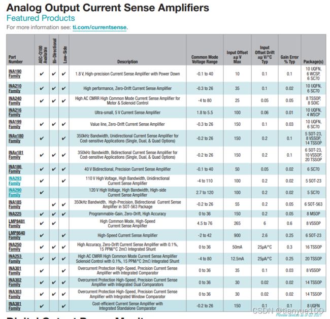
| Selection guide | Current Sense Amplifiers (Rev. E) | 20 Sep 2021 | |
| Technical article | Solving the multidecade current-measurement challenge in your 48-V BMS application | 14 Jun 2021 | |
| Application note | High-Side Motor Current Monitoring for Over-Current Protection (Rev. B) | 23 Feb 2021 | |
| Technical article | How current-sense amplifiers monitor satellite health | 08 Feb 2021 | |
| Application note | Current Sensing in an H-Bridge (Rev. B) | 05 Feb 2021 | |
| Application note | Shunt-Based Current-Sensing Solutions for BMS Applications in HEVs and EVs (Rev. B) | 02 Feb 2021 | |
| Application note | Current Measurements in Power Supplies (Rev. B) | 29 Dec 2020 | |
| Application note | High-Side Drive, High-Side Solenoid Monitor With PWM Rejection (Rev. C) | 04 Dec 2020 | |
| Functional safety information | INA240-Q1 Functional Safety, FIT Rate, Failure Mode Distribution and Pin FMEA (Rev. A) | 23 Mar 2020 | |
| E-book | Simplifying Current Sensing (Rev. A) | 09 Jan 2020 | |
| Application note | Evaluating Current Sensing Amplifiers in Body Control Modules Using Simulation | 16 Dec 2019 | |
| Technical article | Current-sensing dynamics in automotive solenoids | 01 Nov 2019 | |
| Application note | High-side, bidirectional current-sensing circuit with transient protection (Rev. A) | 19 Feb 2019 | |
| Technical article | A key to accurate system thermal management: monitoring both current flow and temperature | 04 Oct 2018 | |
| Application note | Dual Motor Ctl Using FCL and Perf Analysis Using SFRA on TMS320F28379D LaunchPad (Rev. A) | 20 Mar 2018 | |
| Application note | Performance Analysis of Fast Current Loop (FCL) in Servo | 06 Mar 2018 | |
| Application note | Low-Drift, Low-Side Current Measurements for Three-Phase Systems (Rev. B) | 05 Sep 2017 | |
| User guide | INA240 EVM User's Guide (Rev. A) | 17 Jul 2017 | |
| Application note | Benefits of Intergated Low Inductive Shunt for PWM Applications | 17 Jun 2017 | |
| Application note | Precision LED Brightness and Color Mixing With Discrete Current Sense Amplifiers | 28 Feb 2017 | |
| Application note | Current Sensing for Inline Motor-Control Applications | 20 Oct 2016 |
Low-Drift, Precision, In-Line Motor Current Measurements With PWM Rejection (Rev. C)
https://www.ti.com/lit/an/sboa160c/sboa160c.pdf?ts=1649240887941&ref_url=https%253A%252F%252Fwww.ti.com%252Fproduct%252FINA240-Q1


For other systems, such as electronic power steering (EPS), precise current measurements are needed to provide the required feedback control to the torque assist system.
The INA253features all of the performance benefits of INA240 amplifier with the inclusion of integrated shunt. The integrated shunt is a low inductive, precision, 2mΩ 0.1% with a temperature drift of <15ppm/°C. The INA253 is the most accurate current sense amplifier that eliminates the error introduced due to shunt and parasitic introduced due to the layout.

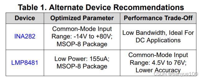
Alternate Device Recommendations
Depending on the necessary system requirements, there may be additional devices that provide the needed performance and functionality. The INA282 is able to measure very precisely large common-mode voltages that do not change as quickly as what typically is seen in PWM driven applications making it ideal for high voltage DC applications. The LMP8481 is a bi-directional current sense amplifier used for high common-mode voltages that do not require the amplifier to include ground within the input voltage range.
Current Sensing in an H-Bridge (Rev. B)
https://www.ti.com/lit/an/sboa174b/sboa174b.pdf?ts=1649169087535
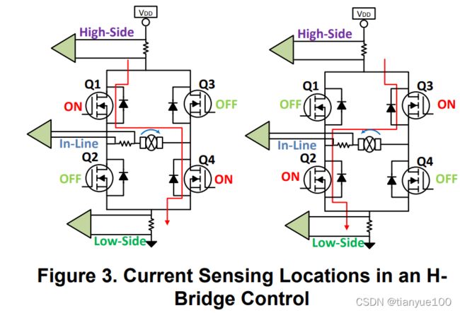
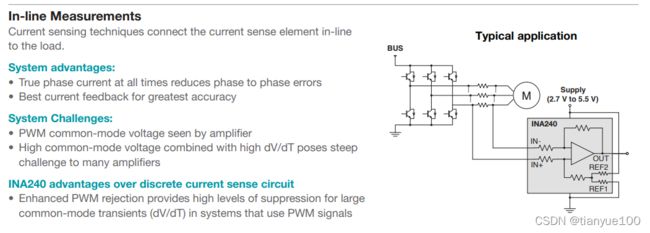
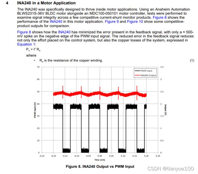
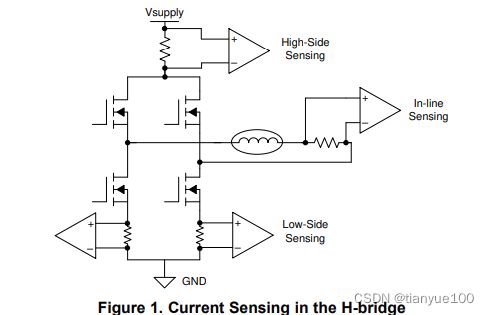
The INA240 current sense amplifier can operate from a common mode voltage ranging from -4V to 80V. In a H-bridge application the INA240 can be used regardless of whether the measurement location is high-side, in-line or low-side. A low offset of (25µV) and low voltage offset drift (0.25µV/°C) combined with a low gain error (0.2%) and gain drift (2.5ppm/°C) makes it applicable for precise measurements regardless of system temperature. In addition to high performance DC specifications, the INA240 is also designed to operate and reject dv/dt transients enabling real time load current measurements at the in-line measurement location. The system level benefits of in-line sensing enables higher efficiency by lowering the processing power requirements for closed loop control system.
SBOA160 Low-Drift, Precision, In-Line Motor Current Measurements With Enhanced PWM RejectionSBOA176 Switching Power Supply Current Measurements
SBOA163 High-Side Current Overcurrent Protection Monitoring
SBOA187 Current Mode Control in Switching Power Supplies
Current Sensing for Inline Motor-Control Applications
https://www.ti.com/lit/an/sboa172/sboa172.pdf?ts=1649240415771&ref_url=https%253A%252F%252Fwww.ti.com%252Fproduct%252FINA240-Q1

Evaluating Current Sensing Amplifiers in Body Control Modules Using Simulation
https://www.ti.com/lit/an/slya047/slya047.pdf?ts=1649240404419&ref_url=https%253A%252F%252Fwww.ti.com%252Fproduct%252FINA240-Q1
1 Introduction

The BCM will rely on multiple types of IC drivers to control, energize, and monitor loads throughout the vehicle. Many of these drivers can be quite complex and can monitor load current for several possible events: over-current protection (OCP), open-load detection, under-voltage lockouts, over-voltage protection, and so on. While this integration can save on board space and design, the performance and accuracy of integrated current sensing and event detection times can be far inferior to the capabilities of using current sense amplifier solutions. Additionally, it might prove beneficial to the system or host to accurately monitor load currents even when no fault event is present.
This report will detail how to use CSAs for monitoring various loads controlled by the BCM including Hbridge controller for brushed DC and stepper motors, as well as, monitoring LED current. As a complement this document will also show how to quickly develop proof-of-concept circuits using SPICE simulation techniques and models available from TI all within the free TINA-TI simulation environment.
2 Overview of Current Sense, Difference, Instrumentation, and Operational Amplifiers
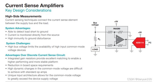
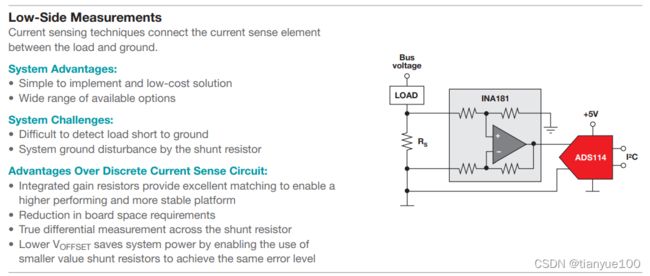
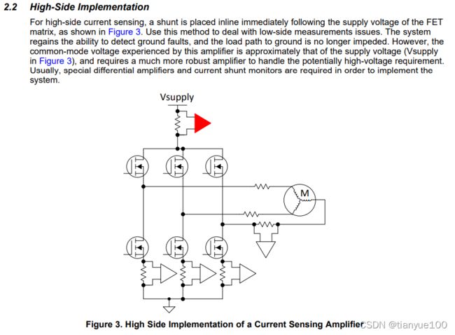
One of the main differences between CSAs and instrumentation amplifiers and op amps is the input common-mode voltage (VCM) rating. CSAs can measure current on a high-side voltage rail with a higher VCM that is independent from the single-ended low voltage supply of the device (VS ). For the BCM, this is crucial because it controls the delivery of the 12-V battery power to loads throughout the car, thus highside switching and monitoring are necessary. Placing current sense amplifiers on the high-side rails on the BCM boards allows for convenient layout for feeding current measurements back to the BCM processor. Many times, low-side sensing at the BCM board is not possible since the car chassis is the ground return path.
Current sense amplifiers also differ from closely related difference amplifiers. The internal resistor network of difference amplifiers is comprised of resistors trimmed to absolute values. Thus, input resistors allow for an extended VCM range; however, this range is not completely independent of the supply voltage and cost usually increases for difference amplifiers. Current sense amplifiers contain an input bias stage before the input resistors. This input stage is what allows for the VCM range of the current sense amplifiers to be completely independent of VS .
3 Current Sense Amplifiers and Integrated Current Sensing of High-Side Switches and Driver
High-side switching ICs can deliver power to loads with a large input voltage range. Many high-side switches (HSS) have integrated current sensing circuitry; however, this can increase the HSS cost and the accuracy of these current measurements is inferior to the accuracy and high-dynamic range achievable with a CSA. This makes CSAs ideal for low-current monitoring, power monitoring, and detecting open loads.
Some motor drivers and antenna LDOs also possess internal amplifiers for low-side current sensing, but once again, accuracy is not as good as using a dedicated CSA. Additionally, amplifier gain and bandwidth can be limited, so a larger shunt resistor is needed, resulting in greater power losses.
4 Current Sensing for the H-bridge
Brushed DC (BDC) motors are prevalent for positioning many light loads in the vehicle. Motor current is usually provided from a half or full bridge connected to a battery. These examples will highlight using the INA180-Q1 and INA181-Q1 to measure low-side BDC current.
DC current is used to keep the motor running in a single direction, but current ripples occur as adjacent commutators are shorted during motion. This results in a small AC current ripple superimposed on the DC current driving the motor. Detecting these ripples will provide information on motor speed and position.
Let’s consider how to measure low-side ripple-current on a full-bridge for a single BDC motor. DC current varies from 1 A to 20 A, and current is not pulse-width modulated (PWM). Ripple current can peak at 0.83 A and occurs at 333 Hz. A 5-V power rail is available. This example assumes the current ripple shape and amplitude were measured directly in the system.
First, create the current ripple waveform in a numerical programmer such as Microsoft Excel. Equation in Figure 2 dictates the shape of a single current ripple. It allows designer to model the current ripple as a piece-wise function with a linear charging half and then a logarithmic discharging component. TS represents the sample time of the function, N is the number of points, IPeak is the peak-to-peak AC-coupled amplitude in Amps, λ is the discharging time constant, and α is small current value to set the final discharging point before the ripple repeats.

Place a Current Generator TINA block into simulation, double-click it, and then click on the Signal text and ellipsis soft-key to open the Signal Editor window. Click the Arbitrary Waveform soft-key and copy and paste the time and current values directly into the waveform text window.

This circuit can require some iterative design to balance the CSA measuring from 1 A to 20 A while also amplifying the ripple without saturating the output of the device. As a start, minimize the shunt resistor to the smallest resistance that can be accurately sensed within manufacturer’s capability. This helps minimize power dissipation.
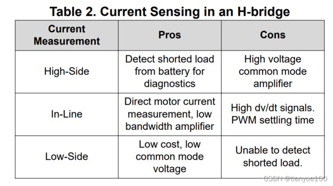
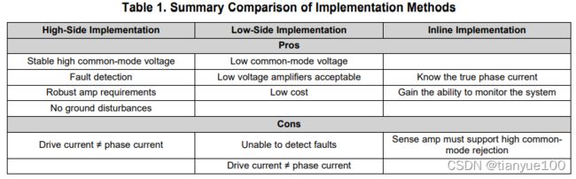
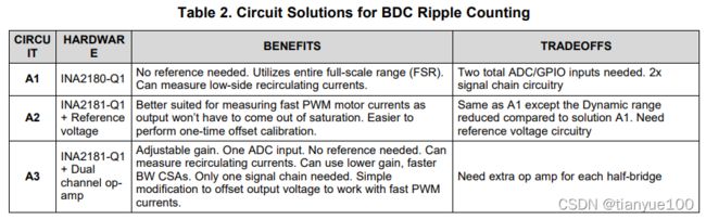
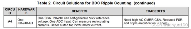
Table 2 is the summary of four possible solutions. Please keep in mind these solutions do not include extra signal chain/conditioning circuitry, however, an example signal chain is shown and can be applied to all of these solutions.
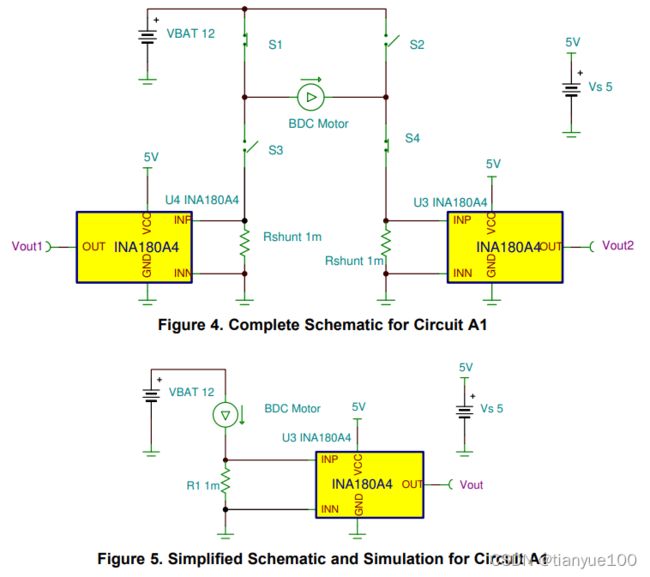
5.1 Circuit A1 - One Low-side, Unidirectional INA2180-Q1 (or Two INA180-Q1)
This is the basic solution where one INA180-Q1 is used for each half-bridge leg. The INA180 is unidirectional so it does not have a reference pin to offset the output voltage and cannot measure bidirectional current alone. However, in this solution, one of the INA180-Q1s can measure low-side recirculating current while the other is saturated with a negative shunt voltage.
Figure 4 shows the complete circuit, but is simplified into a more practical simulation schematic in Figure 5. Executing transient simulations with open switches and floating amplifier inputs requires more setup time and simulation time. From now on, in this document, the simplified schematic is shown and used to generate waveforms since each bridge will have the same current. Figure 6 and Figure 7 show the transient simulation results of Circuit A1.

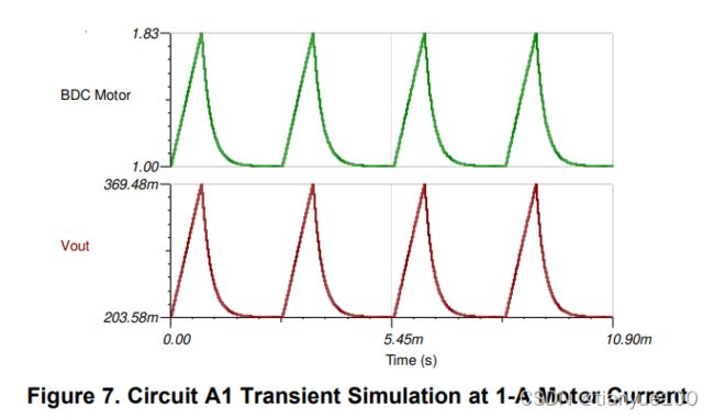
The transient simulations demonstrate that the INA180 can amplify an 830 mA ripple into a 166 mV output ripple (VOUT, RIPPLE) over a 1 A to 20 A DC range using a 1-mΩ shunt resistor. Keep in mind that many BDC motors do not operate as high as 20 A. If the 20-A operating current requirement is lower for an application, then RSHUNT and VOUT, RIPPLE can be increased.
Note that the remaining signal chain design is heavily dependent upon customer’s system requirements. Although, given the accuracy of the models, an engineer can take these simulations and add filtering/amplification circuitry or SAR ADC front-end models to the VOUT node. Many CSA models incorporate bandwidth and closed-loop output impedance (ZOUT) behavior (among other things), which are needed to generate realistic signal chains.
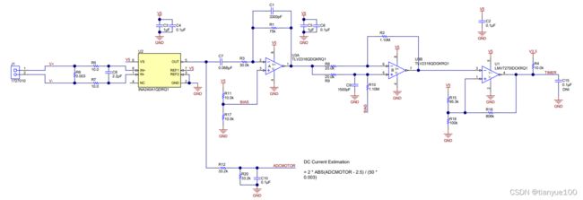
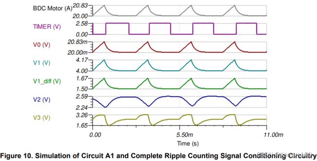
An example signal chain for counting ripple currents from the TI Design TIDA-01421 is shown in Figure 8. The purpose of this signal chain is to convert each ripple into countable pulses for a digital I/O pin. Figure 9 combines the schematics from Figure 5 and Figure 8, and the complete transient simulation is shown in Figure 10.
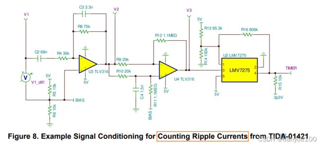
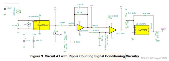
Note that this same signal chain can be used for all of the following circuit solutions and all simulation files are included with this design.
5.2 Circuit A2 – One Low-side, Bidirectional INA2181-Q1 (or Two INA181-Q1s)
The second solution shown in Figure 11 is almost the same as Circuit A1, except the INA2180-Q1 is replaced by the INA2181-Q1, the gain is reduced from 200 V/V to 100 V/V, and the output is offset by 2.5 V. The bidirectional versions of any CSA have the reference pin available to drive so that the VOUT can be offset, allowing for both positive and negative currents to be measured.
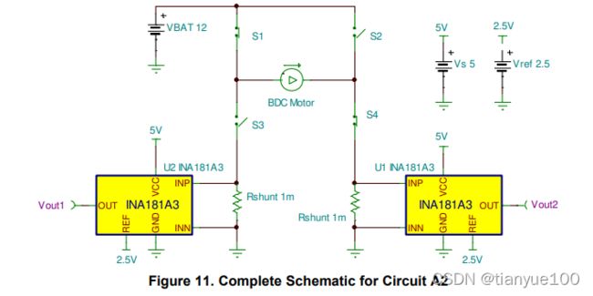
The key benefit of offsetting the output voltage is avoiding output saturation when the motor current is ≤ 0 A. If the output is in saturation, then there is an extra delay (overload recovery time) during an input step response. This delay time becomes especially important when the motor current is pulse-width modulated (PWM) or duty cycles become very short. These scenarios give less time for the output to settle and ripples to be counted completely. Figure 12 and Figure 13 are the transient simulation results of Circuit A2.
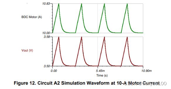

The tradeoffs of Circuit A2 are a compressed VOUT, RIPPLE voltage (83 mV) and extra circuitry to provide the VREF voltage. Referencing the INA2181 to its mid-supply (2.5 V) is usually done because it is cheaper and the positive and negative load currents are symmetrical; however, the recirculating currents for BDC motors are not as high as the positive phase current. Thus, if one wants to maximize their dynamic range, then measuring and characterizing these recirculating currents is necessary to determine the correct value for VREF. Note that in Figure 13, the full-scale range of DC motor current has now expanded to ±20 A with the mid-supply reference.
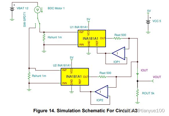
5.3 Circuit A3 – One Low-side, Bidirectional INA2181-Q1 Converted into Current-output with Two Op Amps
The next circuit solution shown in Figure 14 transforms the CSAs from voltage-output to current-output circuits and then sums the current outputs together. This procedure is based off the Howland Current Pump and the design procedure for it can be found here.
One benefit here is reducing the ADC input count needed to measure current for each half-bridge. This is possible because the circuit that is sensing 0 A does not add anything to the output current signal, thus the total current output only reflects the current of one half-bridge at a time.
Another benefit is that the load resistor that converts the output current to ground-referenced voltage can be relatively low-impedance and does not interact with downstream signal chain or SAR ADC operation. ROUT also provides the ability to adjust overall circuit gain. The drawback of Circuit A3 is that measurement of each leg is indistinguishable of the other, and op amp buffers in the feedback are necessary for the circuit to maintain high common-mode rejection (CMR). Figure 12 and Figure 16 shows the simulation results for Circuit A3.


Note that the amplified ripple is the same magnitude as seen in Circuit A1 simulations.
One additional benefit with this circuit is the ability to decrease settling time by including the optional CSET capacitors (see Figure 17). These work as feedforward caps that boost output response time at the expense of output overshoot. The CSET value should be chosen carefully and can be experimented with using the TINA simulation environment given the CSA models have the correct ZOUT and closed-loop gain (ACL).
Another benefit of Circuit A3 is that the output voltage node can be offset by adding one resistor or current source. Offsetting the VOUT node is effectively the same as providing a reference voltage for a bidirectional CSA. Doing this yields the same benefits as Circuit A2, where the output is always in the linear region and can react as quickly as possible to step inputs from PWM motor currents. Figure 17 shows both optional modifications of Circuit A3.
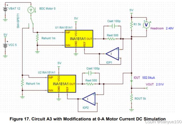
One significant drawback to Circuit A3 with the offset output (Figure 17) is the loss of dynamic range due to the headroom voltage. The headroom voltage must remain high enough so that the INA181 is not swinging too close to its supply rail (VS ) and the VCM of the op amp is not approaching the maximum operating value. The same is true for the swing-to-ground of the INA181 and the minimum operating VCM of the op amp.
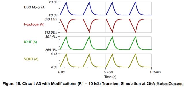
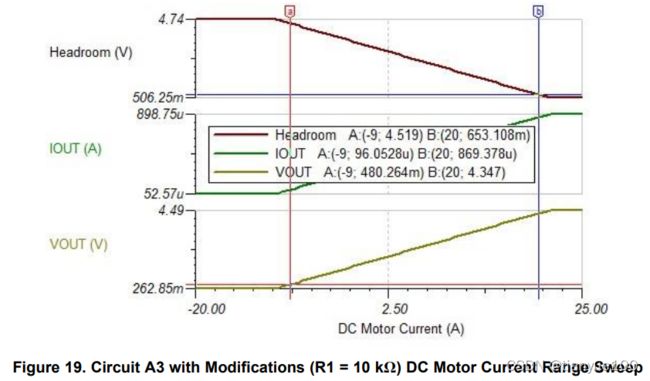
Offsetting the VOUT to 2.5 V in Figure 17 results in a reduced dynamic range of ±17-A motor current; however, given that recirculating currents probably do not approach the motor rating, R1 can be increased to 10 kΩ to shift the dynamic range to -9 A to +20 A where VOUT ranges from 480 mV to 4.35 V, respectively. The circuit behavior after changing R1 to 10 kΩ can be seen in Figure 18 and Figure 19. After making this change, the VOUT, RIPPLE voltage becomes 110 mV.
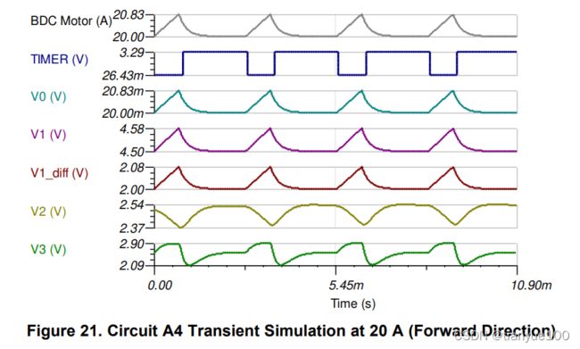
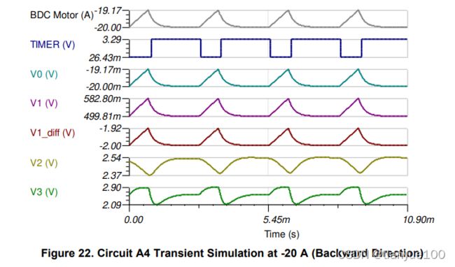
5.4 Circuit A4 – One In-line, Bidirectional INA240-Q1
This circuit solution is used in the TI Design TIDA-01421 and moves the position of the CSA to in-line with the bridge. Specifically chosen for its unique PWM rejection circuitry and thus high AC CMR, the INA240 is the best choice for this application, since the output can settle quickly after phase current switches direction and VCM changes rapidly.
The INA240 is a very accurate device (maximum 25 µV offset) with good bandwidth (400 kHz). Furthermore, the INA240 is bidirectional, so only one device is needed to measure all phase and recirculating currents.
Using only one CSA for all currents has the drawback of a reduced dynamic range, compressed VOUT, RIPPLE, and increased shunt power dissipation. The measured VOUT, RIPPLE for the reference design ranged from 100 mV to 250 mV depending on battery voltage and motor torque. While this is greater than the 166 mV ripple in the previous solutions A1 and A3, it was accomplished at the expense of higher shunt power dissipation and a reduced motor current range of ±16 A.
For the sake of comparison, the shunt resistor can be reduced to 1 mΩ and the INA240A3 (gain of 100 V/V) can be substituted in to yield the simplified schematic in Figure 20. This is effectively the same schematic as Circuit A2, however, there is no way to increase VOUT, RIPPLE. This is because the INA240 must remain referenced at mid-supply to measure both phase currents since this is an in-line application. Figure 21 and Figure 22 show the entire transient simulations with the 830-mA current ripple and motor current at 20 A in both motor directions.

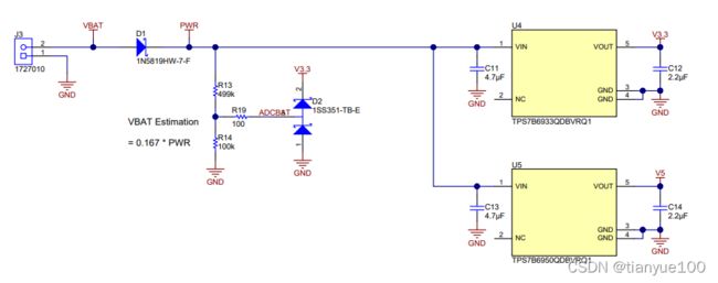
LMV7275-Q1 Automotive Single 1.8-V Low Power Comparator With Rail-to-Rail Input
6 High-Side Stepper Motor Stall Current Detection
Detecting a motor stall is useful to determine if there is a mechanical fault condition, or if the motor has reached its final destination. If a motor is stalling, the motor current increases. This example uses a current sense amplifier to measure high-side current, which allows a control system to detect a stall by making a decision on the peak current. The engineer must characterize the stall current sufficiently to determine an appropriate stall current threshold.
Consider the example of measuring high-side current for two H-bridges driving current for a bipolar stepper motor as shown in Figure 23. A driver and algorithm control the switching, so assume continuous phase current lasts for 2.5 ms and the FET ON pulse is separated by 20 µs of dead time. This is a nonoverlap stepper motor control example.

Placing the shunt resistor (RSHUNT) before or after the bulk capacitance (CBULK) makes a difference in the current amplitude since the bulk capacitor is responsible for keeping the supply voltage stable during switching. There are pros and cons, but inserting the shunt in between CBULK and the shared high-side supply trace allows you to sense the exact motor current. As always, it is best to measure these currents with hardware first so the real current waveform can be incorporated into simulation.
The simulation circuits for this section models the stepper motor as a resistor and inductor. To simplify the operation of the H-bridge, the simulation uses just one time-controlled switch ("FET"). This emulates the high-side current of both H-bridges. Another time-controlled switch ("Stall") suddenly increases motor current at 6.1 ms simulation run-time.
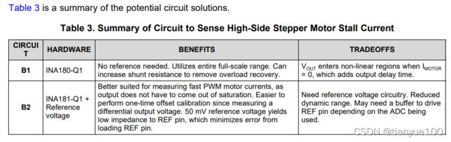
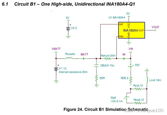
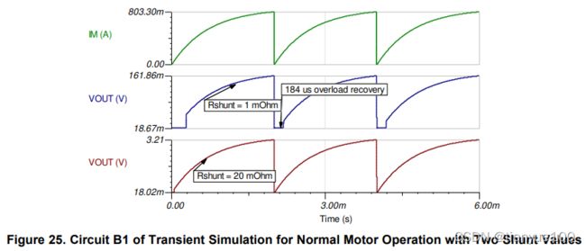
Circuit B1 shown in Figure 24 is most likely the best option for measuring stepper motor stall current. Despite the occurrence of output saturation when motor current is 0 A during H-bridge dead time, there is still plenty of time for the INA180-Q1 to catch up for this relatively slow motor. Additionally, as shown in Figure 25, if the overload recovery time must be avoided, the engineer can increase the shunt resistance to 20 mΩ which accelerates the shunt voltage rise and forces the INA180 out of saturation quicker.
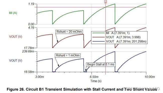
An additional benefit of using a larger shunt resistor is the difference between VOUT for nominal and stall currents increases as shown in Figure 26. When RSHUNT is 1 mΩ, the difference in VOUT between the normal 800-mA and 1-A stall currents is 201.3 mV - 161.9 mV = 39.4 mV. This delta becomes 788 mV for a 20-mΩ shunt. Therefore, increasing RSHUNT increases current measurement resolution and makes the system more immune to potential current transients or noise. The obvious tradeoff is the increase in power loss.
6.2 Circuit B2 – One High-side, Bidirectional INA181-Q1
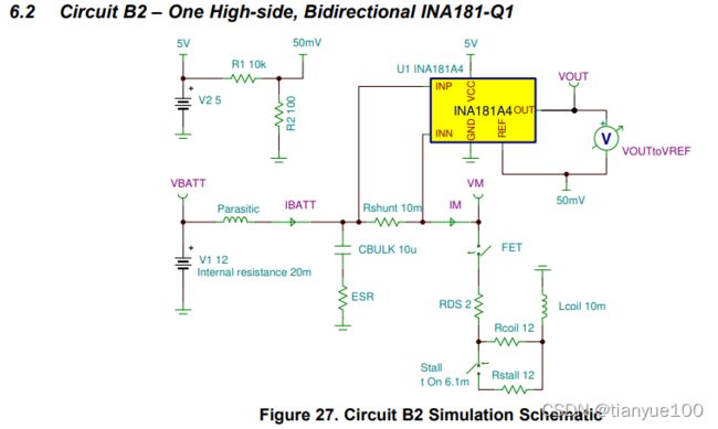
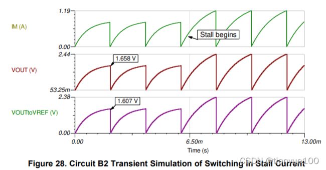
Circuit B2 (shown in Figure 27) is the same as B1, except the bidirectional INA181-Q1 is used so a reference voltage can offset VOUT. This scheme is only necessary if there is pulse-width modulation (PWM) to be sensed or if the stepping is done at very fast speeds (>20 kHz) where overload recovery time cannot be accepted. Another benefit with Circuit B2 is that a one-time offset calibration can be performed at every start-up, simply by reading VOUT with no load current. If measuring small shunt voltages is important, then offset calibration reduces measurement error significantly. Note how in Figure 28, the INA181 is responding immediately to the changing motor current since it is offset by 50 mV and is always in the linear region. The VOUT waveform for Circuit B2 is actually the differential output measurement of the INA181.
7 High-Side Averaging PWM LED Current Sensing
The accuracy of a CSA provides the ability to sense undercurrent events, which is important for ensuring sufficient lighting levels for LEDs. When driving LEDs with a PWM current, measuring peak current can become unfeasible for very low duty cycles. Once the ON current time falls below a microsecond, most current sense amplifiers will fail to settle to an accurate voltage level before current falls back to 0 A.
One way around this is to average the shunt voltage signal before amplifying with a CSA. To average the shunt voltage, a differential RCR, PI filter is used at the input of the CSA. Many CSAs are low-input impedance (2 kΩ to 4 kΩ differential) and thus do not work infallibly with input resistors since this reduces effective gain and increases gain error. The increase in gain error is due to the fact that the CSA internal resistors are trimmed to a precise ratio, not an absolute value. Choosing a high input-impedance CSA, such as the INA190-Q1 or INA186-Q1, can mitigate this issue.
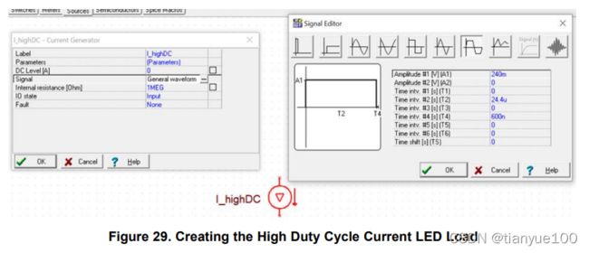
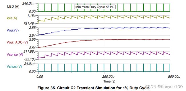
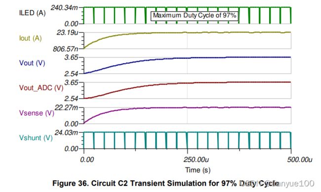
Consider how to measure high-side LED current from a PWM, current-controlled LED driver. The current frequency is 40 kHz (25 µs period), the highest duty cycle is 97% (24.36 µs ON time), and the lowest duty cycle is 1% (240 ns ON time). The LED load waveform shown in Figure 29 is created by double-clicking a current generator source, changing the signal to “General Waveform”, and setting the current amplitude, ON and OFF times.
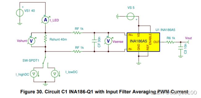
7.1 Circuit C1 – 42-V High-impedance CSA (INA186-Q1) with Input Filter
The solution shown in Figure 30 is used for the high-input impedance CSA INA186-Q1, or its more accurate version, the INA190-Q1. This device has an input differential impedance of 4.6 MΩ, so device performance is not significantly affected by large input impedance. Using the equation in the INA186-Q1 data sheet and setting differential input impedance to 4.6 MΩ, the system designer calculates only a 43.5 m% increase in gain error.
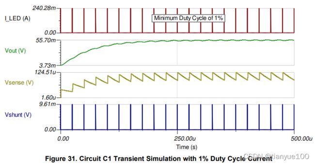
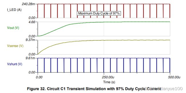
The transient simulations of Circuit C1 (Figure 31 and Figure 32) show that the filtered input sense voltage (VSENSE) varies from ~100 µV to 9.37 mV, which is within the input dynamic range of the INA186A5-Q1. The input filter has a cutoff frequency of 2.654 kHz, or 1/(4*PI*RF *CF ). Try to reduce the tolerances of input filter components so averaged current values remain consistent.
7.2 Circuit C2 – 60-V Transconductance CSA (INA169-Q1) with Input Filter and Output Offset Modification (Requires Offset Calibration)
For LED boost drivers, the high-side voltage can be much higher than 42 V. Applications requiring highside measurements up to 60-V need a high-voltage CSA. This example uses the INA169-Q1. While the INA16x/INA13x-Q1 families do not have a high input impedance like the INA186-Q1, the transconductance architecture (see Figure 33) allows the user to calculate the exact effective gain of the circuit once a known input resistance is used. Note that RG1 resistors are trimmed to the exact resistance reported in data sheet.
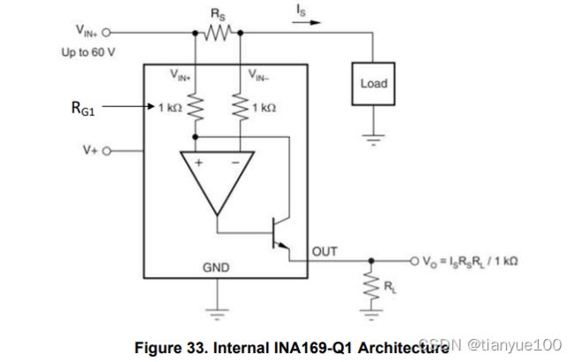
Figure 34 is the simulation schematic for the Circuit C2, showing the added input resistors (RF ) to the INA169. To calculate the new circuit gain when using an input filter with the INA169, simply add RF to RG1 and take the reciprocal to get the new transconductance value. For Circuit C2, the new gain is 1 / (1 kΩ + 50 Ω) = 952.38 µA/V. The INA169 has a substantial maximum input offset of ±2 mV, thus modifications must be made to negate this offset. One way is to offset the output of the amplifier (see data sheet) by connecting a resistor from OUT to its 5-V supply rail. While this brings the output into the linear region for low LED currents, the extra step of offset calibration is needed to determine the zero-current voltage of the circuit. This is the only practical way to negate resistor tolerance and IC offset errors.

8 Summary
This document has covered how to choose a CSA that fits a range of requirements when monitoring loads associated with electronic control units, specifically in the automotive space. Several complete current sensing solutions were suggested and verified in TINA-TI simulation.
9 References
A special thanks to contributions of Dan Harmon and Steven Loveless.
• TI Design TIDA-01421 Automotive Brushed-Motor Ripple Counter Reference Design for Sensorless Position Measurement