HCIP综合实验 OSPF RSTP ISIS BGP 超详细
综合实验
一、交换部分
1、接口配置为access、trunk
2、MUX VLAN
3、配置Rstp协议
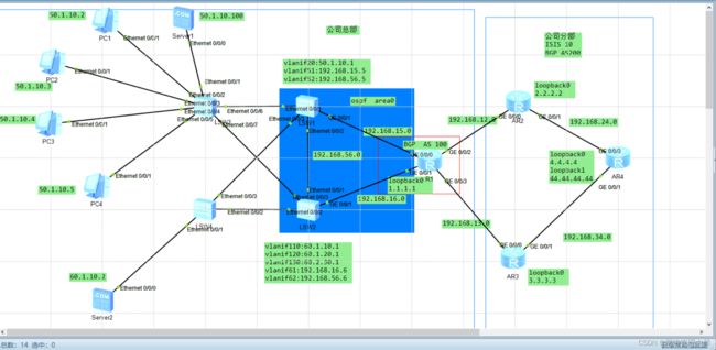
二、路由部分
1、配置OSPF路由协议
2、OSPF路由引入
3、区域认证
4、配置IS-IS路由协议
5、配置BGP路由协议
划分多元VLAN MUX VLAN
Sever 1为主VLAN
PC1 PC2 设置为互通型
PC3 PC4 设置为隔离型
Server 2 是基于MAC地址划分VLAN,当他接入LSW4,就放到110 这个VLAN (MAC地址绑定)
LSW1、LSW2 和 R1运行 OSPF
R2\R3\R4 运行 ISIS
相互引入
LSW3 和 LSW1 做成access,设置为VLAN 20
基本的ip地址配置
1、基本配置
R1:
sys
sysname R1
int loop 0
ip address 1.1.1.1 24
int g0/0/0
ip address 192.168.15.1 24
int g0/0/1
ip address 192.168.16.1 24
int g0/0/2
ip address 192.168.12.1 24
int g0/0/3
ip address 192.168.13.1 24
q
R2:
sys
sysname R2
int loop 0
ip address 2.2.2.2 24
int g0/0/0
ip address 192.168.12.2 24
int g0/0/1
ip address 192.168.24.2 24
q
R3:
sys
sysname R3
int loop 0
ip address 3.3.3.3 24
int g0/0/0
ip address 192.168.13.3 24
int g0/0/1
ip address 192.168.34.3 24
q
R4:
sys
sysname R4
int loop 0
ip address 4.4.4.4 24
int loop 1
ip address 44.44.4.4 24
int g0/0/0
ip address 192.168.24.4 24
int g0/0/1
ip address 192.168.34.4 24
q
S1:
sys
sysname S1
int vlanif 20
ip address 50.1.10.1 24
int vlanif 51
ip address 192.168.15.5 24
int vlanif 52
ip address 192.168.56.5 24
q
S2:
sys
sysname S2
int vlanif 110
ip address 60.1.10.1 24
int vlanif 120
ip address 60.1.20.1 24
int vlanif 130
ip address 60.2.30.1 24
int vlanif 61
ip address 192.168.16.6 24
int vlanif 62
ip address 192.168.56.6 24
q
一、交换部分
1.接口配置为Access、Trunk
配置LSW1 和 LSW3相连接的接口为access端口,允许VLAN 20通过
配置LSW1 和LSW4的接口,配置LSW2和LSW3的接口,配置LSW2和LSW4的接口,为Trunk,允许VLAN 10、VLAN 20、VLAN 30、VLAN 110、VLAN 120、VLAN 130通过。
LSW1:
int e0/0/1
port link-type access
port default vlan 20
int e0/0/3
port link-type trunk
port trunk allow-pass vlan 10 20 30 110 120 130
LSW2:
int e0/0/2
port link-type trunk
port trunk all vlan 10 20 30 110 120 130
int e0/0/3
port link-type trunk
port trunk all vlan 10 20 30 110 120 130
LSW3:
int e0/0/6
port link-type access
port default vlan 20
int e0/0/7
port link-type trunk
port trunk all vlan 10 20 30 110 120 130
LSW4:
int e0/0/3
port link-type trunk
port trunk all vlan 10 20 30 110 120 130
int e0/0/2
port link-type trunk
port trunk all vlan 10 20 30 110 120 130
在LSW1和LSW2上将两个接口划分到相应的VLAN中
LSW1:
int e0/0/2
port link-type access
port default vlan 52
int g0/0/1
port link-type access
port default vlan 51
LSW2:
int e0/0/1
port link-type access
port default vlan 62
int g0/0/1
port link-type access
port default vlan 61
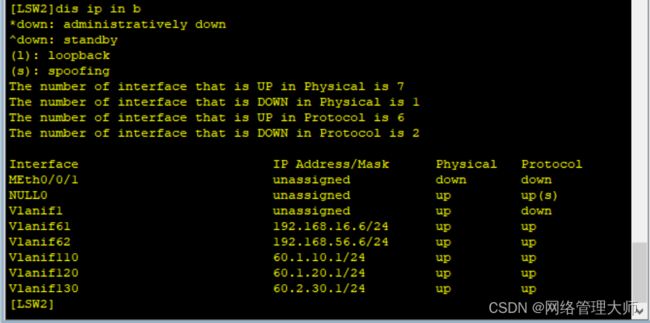
dis ip int brief
Server 2属于VLAN 110的,要求Server 2无论从哪个接口接入SW4都必须属于VLAN 110,为此,基于MAC地址将Server 2添加到 VLAN 100
LSW4:(不常用)
vlan 110
mac-vlan mac-address 5489-9823-2167
int e0/0/1
port hybrid untagged vlan all
mac-vlan enable
dis mac-vlan vlan 110

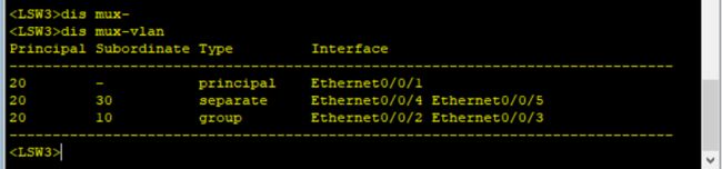
2.MUX VLAN
公司总部园区,公司员工和公司客户都可以访问公司的服务器,公司内部员工之间也可以互相交流,但与公司客户之间是隔离的,不能够相互访问。公司客户与客户之间不能互访,客户与公司员工也不能互访。这样的需求可以通过MUX VLAN来实现。
在交换机SW3 上,配置Server 1所在的VLAN 20为主VLAN,配置公司员工PC1和PC2所在的VLAN 10为互通从VLAN,配置公司客户PC3 和 PC4所在的VLAN 30 为隔离从VLAN。
接口是access才能配置MUX VLAN
LSW3:
vlan 20
mux-vlan
subordinate group 10
subordinate separate 30
int e0/0/1
port mux-vlan enable
port link-type access
port default vlan 20
int e0/0/2
port mux-vlan enable
port link-type access
port default vlan 10
int e0/0/3
port mux-vlan enable
port link-type access
port default vlan 10
int e0/0/4
port mux-vlan enable
port link-type access
port default vlan 30
int e0/0/5
port mux-vlan enable
port link-type access
port default vlan 30
pc间的测试验证
3.配置RSTP协议
为了防止公司总部园区网的二层环路,配置所有的交换机工作在RSTP模式。
SW1 为根交换机,SW2为备份根交换机
LSW1:
stp mode rstp
stp root primary
LSW2:
stp mode rstp
stp root secondary
[LSW3]stp mode rstp
[LSW4]stp mode rstp
为了提高网络的稳定性,配置根保护功能,使得无论网络发生什么变化,根交换机的角色都不会改变。根保护是指定端口的特性,当端口橘色是指定端口时,根保护才生效。
在交换机与交换间的 指定端口启动 根保护 连PC的DP不用做
dis stp brief
LSW2:
int g0/0/2
stp root-protection
int g0/0/3
stp root-protection
SW2的g0/0/4端口是连接的上行路由器,SW3 SW4的指定端口连接的是PC或服务器,因此这些端口无需配置根保护功能。
LSW1:
int g0/0/3
stp root-protection
如果有攻击者伪造拓扑变化BPDU报文来恶意攻击二层网络,则交换机在短时间内会收到大量的拓扑变化BPDU报文,这会给交换机的处理工作造成很大的复旦。为此,可以通过配置 TC-BPDU 保护功能来解决这个问题
LSW1 LSW2 LSW3 LSW4:
stp tc-protection
stp tc-protection threshold 2
为了加快收敛速度,将交换机SW3 和 SW4连接PC服务器的端口配置为边缘端口
LSW3:
int e0/0/1
stp edged-port enable
int e0/0/2
stp edged-port enable
int e0/0/3
stp edged-port enable
int e0/0/4
stp edged-port enable
int e0/0/5
stp edged-port enable
LSW4:
int e0/0/1
stp edged-port enable
bpdu保护
stp bpdu-protection
[LSW3]stp bpdu-protection
[LSW4]stp bpdu-protection
二、路由部分
1.配置OSPF路由协议
在R1、LSW1和LSW2 上配置OSPF
R1:
ospf router-id 1.1.1.1
area 0
net 1.1.1.1 0.0.0.0
net 192.168.15.1 0.0.0.0
net 192.168.16.1 0.0.0.0
LSW1:
ospf router-id 5.5.5.5
area 0
net 192.168.15.5 0.0.0.0
net 192.168.56.5 0.0.0.0
LSW2:
ospf router-id 6.6.6.6
area 0
net 192.168.16.6 0.0.0.0
net 192.168.56.6 0.0.0.0
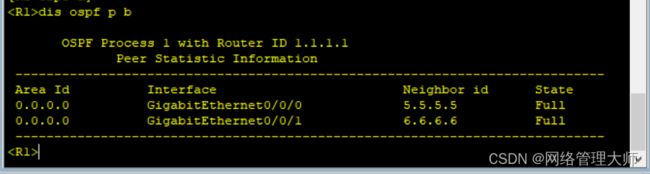
在R1上查看邻居的建立 display ospf peer brief
2.OSPF 路由引入
将LSW1 上的VLAN 20所对应的网段作为外部路由引入OSPF 进程,并进行路由聚合。
将LSW2 上的VLAN 110、VLAN 120和VLAN 130引入进来,并对VLAN 110、VLAN 120进行路由聚合,VLAN 130不聚合。
LSW1:
ospf
import-route direct
asbr-summary 50.1.0.0 255.255.0.0
LSW2:
ospf
import-route direct
asbr-summary 60.1.0.0 255.255.224.0
VLAN 130 不聚合
60.2.30.1 后面做拒绝,写ACL,路由策略。
 3.区域认证
为了提高网络的安全性,R1 LSW1 LSW2 需要相互通过认证才能交换路由信息。
做OSPF的区域认证,简单的明文,密钥为huawei
R1:
ospf
area 0
authentication-mode simple plain huawei
LSW1:
ospf
area 0
authentication-mode simple plain huawei
LSW2:
ospf
area 0
authentication-mode simple plain huawei
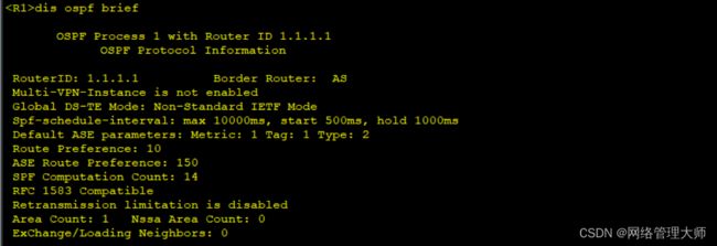
查看一下 < R1 >dis ospf brief
 4.配置 IS-IS 路由协议
在公司分部 R2 R3 R4 上配置,为了减少 IS-IS 邻居关系数量和精简链路状态数据库,R2 R3 R4为level-2路由器
R2:
isis
network-entity 10.0000.0000.0002.00
is-name R2
is-level level-2
int loo0
isis enable
int g0/0/1
isis enable
R3:
isis
network-entity 10.0000.0000.0003.00
is-name R3
is-level level-2
int loo 0
isis enable
int g0/0/1
isis enable
R4:
isis
network-entity 10.0000.0000.0004.00
is-name R4
is-level level-2
int loo 0
isis enable
int loo 1
isis enable
int g0/0/0
isis enable
int g0/0/1
isis enable
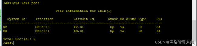
在R4上查看 IS-IS 邻居关系 dis isis peer
 dis ip routing-table
 R4已经通过IS-IS协议获得了 R2 R3的loopback 0网段的路由
5.配置BGP路由协议
在R1、R2、R3、R4上配置BGP协议,EBGP邻居关系采用直连物理接口来建立,IBGP邻居关系采用loopback 0接口来建立
R1:
bgp 100
router-id 1.1.1.1
peer 192.168.12.2 as-number 200
peer 192.168.13.3 as-number 200
R2:
bgp 200
router-id 2.2.2.2
peer 192.168.12.1 as-number 100
peer 4.4.4.4 as-number 200
peer 4.4.4.4 connect-interface loopback 0
peer 4.4.4.4 next-hop-local
R2指了R1和R4 没有指R3,因为R3通过R1环回口也能学习到,可以不指。
R3:
bgp 200
router-id 3.3.3.3
peer 192.168.13.1 as-number 100
peer 4.4.4.4 as-number 200
peer 4.4.4.4 connect-interface loopback 0
peer 4.4.4.4 next-hop-local
R4:
bgp 200
router-id 4.4.4.4
peer 2.2.2.2 as-number 200
peer 2.2.2.2 connect-interface loopback 0
peer 3.3.3.3 as-number 200
peer 3.3.3.3 connect-interface loopback 0
在R4上查看BGP邻居关系
dis bgp peer
为了让公司分部知道公司总部网络的路由,在R1上将OSPF引入BGP进程
R1:
bgp 100
import-route ospf 1
在R2上查看路由 dis ip routing-table
公司总部不希望公司分布访问 60.2.30.0/24网段,因为这是总部财务部门所属的网段,所以公司总部的网络管理员决定在R1上使用路由策略在引入OSPF路由时过滤掉这个网段的路由
R1:
acl 2000
rule permit source 60.2.30.0 0.0.0.255
route-policy 10 deny node 1
if-match acl 2000
route-policy 10 permit node 2
bgp 100
import-route ospf 1 route-policy 10
为了能将公司分部的路由信息通告给公司总部,在R2和R3上将IS-IS路由引入到BGP协议
R2:
bgp 200
import-route isis 1
R3:
bgp 200
import-route isis 1
R1上查看路由表 dis ip routing-table
R1通告BGP接收到了公司分部网络的路由
下发缺省路由
总部交换机SW1和SW2由于没有运行BGP路由协议,所以无法获得公司分部网络的路由。 可以R1上通告OSPF非强制方式下发缺省路由,SW1和SW2通告该缺省路由来访问公司分部网络。OSPF非强制下发缺省路由的条件是,IP路由表中存在非OSPF进程的缺省路由。 因此,可以在R2和R3上配置BGP下发缺省路由给R1,使R1的路由表存在一条来自BGP的缺省路由。
R1:
ospf
default-route-advertise
R2:
bgp 200
peer 192.168.12.1 default-route-advertise
R3:
bgp 200
peer 192.168.13.1 default-route-advertise
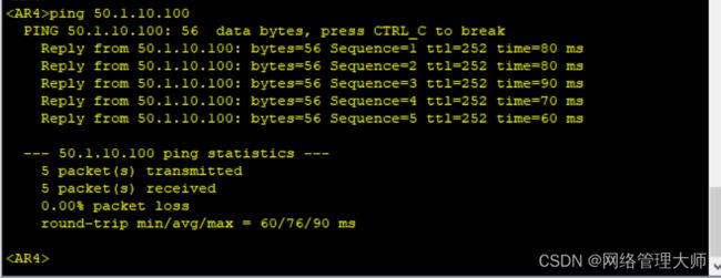
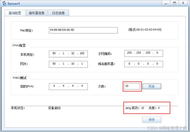
测试连通性