正点原子STM32F103学习笔记(三)——跑马灯
跑马灯实验
库函数
基础知识
- 库函数控制IO口输出高低电平
- 头文件:stm32f10x_gpio.h
源文件:stm32f10x_gpio.c - FWLIB下"misc.c"、“stm32f10x_gpio.c”、“stm32f10x_rcc.c”(涉及到时钟)每个程序必须用到
- 新建"HARDWARE"文件夹,内包含"led.c",包含LED初始化相关代码
重要函数
1个初始化函数:
void GPIO_Init(GPIO_TypeDef* GPIOx, GPIO_InitTypeDef* GPIO_InitStruct);
//对IO口模式(输出速度、上下拉)设置

//第一个参数,七个寄存器,选中某一个IO口,GPIOx有效性为GPIOA-GPIOG
typedef struct
{
  __IO uint32_t CRL;
  __IO uint32_t CRH;
  __IO uint32_t IDR;
  __IO uint32_t ODR;
  __IO uint32_t BSRR;
  __IO uint32_t BRR;
  __IO uint32_t LCKR;
} GPIO_TypeDef;

//第二个参数,对相关参数初始化
typedef struct
{
  uint16_t GPIO_Pin;
  //确定是这一组GPIO下哪个IO口,有效性
  //GPIO_Pin_0
  //GPIO_Pin_1
  //GPIO_Pin_2
  //...
  //GPIO_Pin_15
  //GPIO_Pin_All
  GPIOSpeed_TypeDef GPIO_Speed;
  //确定速度,有效性
  //GPIO_Speed_10MHz = 1
  //GPIO_Speed_2MHz
  //GPIO_Speed_50MHz
  GPIOMode_TypeDef GPIO_Mode;
  //确定模式,有效性
  //GPIO_Mode_AIN = 0x0
  //GPIO_Mode_IN_FLOATING = 0x04
  //GPIO_Mode_IPD = 0x28
  //GPIO_Mode_IPU = 0x48
  //GPIO_Mode_Out_OD = 0x14
  //GPIO_Mode_Out_PP = 0x10 //推挽输出
  //GPIO_Mode_AF_OD = 0x1C
  //GPIO_Mode_AF_PP = 0x18
}GPIO_InitTypeDef;
初始化样例:
GPIO_InitTypeDef  GPIO_InitStructure;

GPIO_InitStructure.GPIO_Pin = GPIO_Pin_5;
//LED0-->PB.5 端口配置
GPIO_InitStructure.GPIO_Mode = GPIO_Mode_Out_PP;
//推挽输出
GPIO_InitStructure.GPIO_Speed = GPIO_Speed_50MHz;
//IO口速度为50MHz
GPIO_Init(GPIOB, &GPIO_InitStructure);
//根据设定参数初始化GPIOB.5
2个读取输入电平函数:
uint8_t GPIO_ReadInputDataBit(GPIO_TypeDef* GPIOx, uint16_t GPIO_Pin);
uint16_t GPIO_ReadInputData(GPIO_TypeDef* GPIOx);
//读取某组GPIO输入电平。实际操作是GPIOx_IDR寄存器
2个读取输出电平函数:
uint8_t GPIO_ReadOutputDataBit(GPIO_TypeDef* GPIOx, uint16_t GPIO_Pin);
uint16_t GPIO_ReadOutputData(GPIO_TypeDef* GPIOx);
4个设置输出电平函数:
//常用前两个
void GPIO_SetBits(GPIO_TypeDef* GPIOx, uint16_t GPIO_Pin);
//输出高,操作BSRR寄存器
void GPIO_ResetBits(GPIO_TypeDef* GPIOx, uint16_t GPIO_Pin);
//输出低,操作BRR寄存器第十六位
void GPIO_WriteBit(GPIO_TypeDef* GPIOx, uint16_t GPIO_Pin, BitAction BitVal);
void GPIO_Write(GPIO_TypeDef* GPIOx, uint16_t PortVal);
写跑马灯实验
步骤
- 使能IO口时钟,开启外设
//在stm32f10x_rcc.c中,有多个外设时钟使能函数 void RCC_APB2PeriphClockCmd(uint32_t RCC_APB2Periph, FunctionalState NewState); /*RCC_APB2Periph有效性 RCC_APB2Periph_GPIOA RCC_APB2Periph_GPIOB RCC_APB2Periph_GPIOC RCC_APB2Periph_GPIOD RCC_APB2Periph_GPIOE RCC_APB2Periph_GPIOF RCC_APB2Periph_GPIOG */ /*NewState有效的 DISABLE和ENABLE */ void RCC_APB1PeriphClockCmd(uint32_t RCC_APB1Periph, FunctionalState NewState); - 初始化IO口模式。调用函数
GPIO_Init(); - 操作IO口,输出高低电平。
GPIO_SetBits();
GPIO_ResetBits();
实操
- 新建HARDWARE文件夹,其中包含LED文件夹,LED文件夹内添加led.h,led.c文件
- Manage Project Items在HARDWARE中添加led.c
- 魔术棒中添加C/C++ 中Include Paths 中增加led.h所在文件夹
- led.h中头文件写函数声明和宏定义
#ifndef __LED_H #define __LED_H void LED_Init(void); #endif - led.c文件,写函数体
#include "LED.h" #include "stm32f10x.h" //使用固件库相关函数都要调用 void LED_Init(void) { GPIO_InitTypeDef GPIO_InitStructure; //定义结构体 RCC_APB2PeriphClockCmd(RCC_APB2Periph_GPIOB,ENABLE); //使能GPIOB时钟 RCC_APB2PeriphClockCmd(RCC_APB2Periph_GPIOE,ENABLE); //使能GPIOE时钟 //也可将前两句写成 //RCC_APB2PeriphClockCmd(RCC_APB2Periph_GPIOB||RCC_APB2Periph_GPIOE,ENABLE); GPIO_InitStructure.GPIO_Mode=GPIO_Mode_Out_PP; //推挽输出 GPIO_InitStructure.GPIO_Pin=GPIO_Pin_5; GPIO_InitStructure.GPIO_Speed=GPIO_Speed_50MHz; GPIO_Init(GPIOB,&GPIO_InitStructure); //GPIOB初始化 GPIO_SetBits(GPIOB,GPIO_Pin_5); //一开始输出高电平,灯熄灭 GPIO_InitStructure.GPIO_Mode=GPIO_Mode_Out_PP; //推挽输出 GPIO_InitStructure.GPIO_Pin=GPIO_Pin_5; GPIO_InitStructure.GPIO_Speed=GPIO_Speed_50MHz; GPIO_Init(GPIOE,&GPIO_InitStructure); //GPIOE初始化 GPIO_SetBits(GPIOE,GPIO_Pin_5); } - main.c
#include "stm32f10x.h" //用到gpio函数操作,所以引用顶层头文件
#include "LED.h"
#include "delay.h"

int main(void)
{
 delay_init(); //调用延时函数前先初始化
 LED_Init();

 while(1)
 {
 	GPIO_SetBits(GPIOB,GPIO_Pin_5);
 	GPIO_SetBits(GPIOE,GPIO_Pin_5);
 	delay_ms(500);

 	GPIO_ResetBits(GPIOB,GPIO_Pin_5);
 	GPIO_ResetBits(GPIOE,GPIO_Pin_5);
 	delay_ms(500);
 }
}
寄存器
步骤
- 使能IO口时钟。配置寄存器RCC_APB2ENR。
寄存器定义在stm32f10x.h中 - 初始化IO口模式。配置寄存器GPIOx_CRH/CRL
- 操作IO口,输出高低电平。配置寄存器GPIOX_ODR或者BSRR/BRR。
实操
- 新建HARDWARE文件夹,其中包含LED文件夹,LED文件夹内添加led.h,led.c文件
- Manage Project Items在HARDWARE中添加led.c
- 魔术棒中添加C/C++ 中Include Paths 中增加led.h所在文件夹
- led.h中头文件写函数声明和宏定义
#ifndef __LED_H #define __LED_H void LED_Init(void); #endif - led.c文件,写函数体
#include "LED.h" #include "stm32f10x.h" void LED_Init(void) { //是能时钟 RCC->APB2ENR|=1<<3; //使能GPIOB,1左移三位,即只使得第三位为1,其他位不变 RCC->APB2ENR|=1<<6; //使能GPIOE //GPIOB.5 50MHz,推挽输出 GPIOB->CRL&=0xFF0FFFFF; //第六个F配置GPIOB.5,清零对应位 GPIOB->CRL|=0x00300000; //或运算不改变0位,将对应四位设置为0011 GPIOB->ODR|=1<<5; //相当于...100000,第六位变成1 //GPIOE.5 GPIOE->CRL&=0xFF0FFFFF; //第六个F配置GPIOB.5,清零对应位 GPIOE->CRL|=0x00300000; //或运算不改变0位,将对应四位设置为0011 GPIOB->ODR|=1<<5; } - main.c
#include "stm32f10x.h"
#include "delay.h"
#include "LED.h"

int main(void)
{
 delay_init();
 LED_Init();

 while(1)
 {
GPIOB->ODR|=1<<5;
GPIOE->ODR|=1<<5;
delay_ms(500);
 GPIOB->ODR=~(1<<5);  //...11011111
 GPIOE->ODR=~(1<<5);
delay_ms(500);
 }
}
位操作
位操作原理:
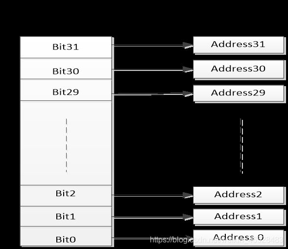
把每个比特膨胀为一个32位的字,当访问这些字的时候就达到了访问比特的目的,比如说BSRR寄存器有32个位,那么可以映射到32个地址上,我们去访问(读-改-写)这32个地址就达到访问32个比特的目的。
哪些区域支持位操作:
其中一个是 SRAM 区的最低 1MB 范围,0x20000000 ‐ 0x200FFFFF(SRAM 区中的最低 1MB)
第二个则是片内外设区的最低 1MB范围,0x40000000 ‐ 0x400FFFFF(片上外设区中最低 1MB)
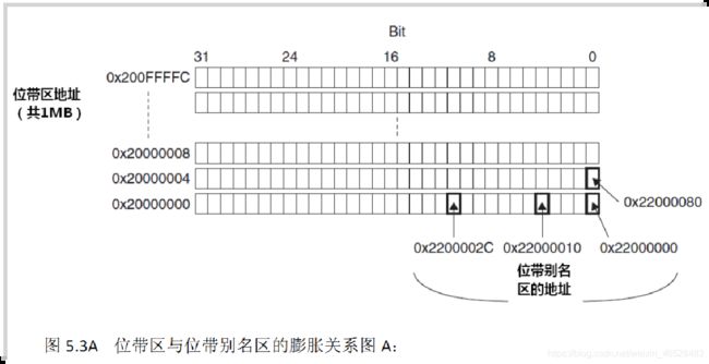
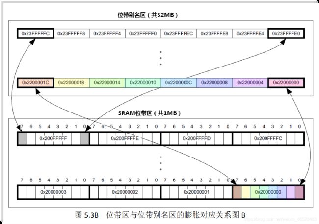
一个bit膨胀为32位的地址,所以1M->32M
// sys.h头文件中包含了位操作的封装
#define PAout(n)   BIT_ADDR(GPIOA_ODR_Addr,n)  //输出
#define PAin(n)    BIT_ADDR(GPIOA_IDR_Addr,n)  //输入

#define PBout(n)   BIT_ADDR(GPIOB_ODR_Addr,n)  //输出
#define PBin(n)    BIT_ADDR(GPIOB_IDR_Addr,n)  //输入

#define PCout(n)   BIT_ADDR(GPIOC_ODR_Addr,n)  //输出
#define PCin(n)    BIT_ADDR(GPIOC_IDR_Addr,n)  //输入

#define PDout(n)   BIT_ADDR(GPIOD_ODR_Addr,n)  //输出
#define PDin(n)    BIT_ADDR(GPIOD_IDR_Addr,n)  //输入

#define PEout(n)   BIT_ADDR(GPIOE_ODR_Addr,n)  //输出
#define PEin(n)    BIT_ADDR(GPIOE_IDR_Addr,n)  //输入

#define PFout(n)   BIT_ADDR(GPIOF_ODR_Addr,n)  //输出
#define PFin(n)    BIT_ADDR(GPIOF_IDR_Addr,n)  //输入

#define PGout(n)   BIT_ADDR(GPIOG_ODR_Addr,n)  //输出
#define PGin(n)    BIT_ADDR(GPIOG_IDR_Addr,n)  //输入
PAout()等控制ODR寄存器
PAin()等控制IDR寄存器
步骤
- 使能IO口时钟。调用函数RCC_APB2PeriphColckCmd();
- 初始化IO口模式。调用函数GPIO_Init();
- 操作IO口,输出高低电平。使用位带操作。
实操
main.c
#include "STM32F10x.h"
#include "led.h"
#include "delay.h"

int main(void)
{
   delay_init();
   LED_Init();

   while(1)
   {
      PBout(5)=1;
      PEout(5)=1;
      delay_ms(300);

      PBout(5)=0;
      PEout(5)=0;
      delay_ms(300);
   }
}