从零开始平衡车,一个一个代码过(代码部分)
 主要用到这些函数,会有一定的顺序来说大多数的函数,其中最后两个是抄的,不用过多解释。
下面是主函数,其中大多数被我注释掉了,因为主函数过多函数,电机会有延迟。
我这里蓝牙后期会改到,USART2中断中,以后会更新。
int main()
{
	OLED_Init();//OLED
	MySerial_Init();//蓝牙
	MyMotor_Init();//电机
	RMyEncoder_Init();//编码器
	LMyEncoder_Init();//编码器
	while(MPU_Init()!=0);//MPU6050
	while(mpu_dmp_init()!=0)//DMP
	{
	}
	OLED_ShowString(1,5,"Da:");
	OLED_ShowString(2,5,"Sp:");
	OLED_ShowString(3,5,"RE:");
	OLED_ShowString(4,5,"LE:");

		while(1)
		{
			mpu_dmp_get_data(&pitch,&roll,&yaw);
//			OLED_ShowSignedNum(1,1,pitch,3);
//			OLED_ShowSignedNum(2,1,roll,3);
//			OLED_ShowSignedNum(3,1,yaw,3);
//

//			if(USART_GetFlagStatus(USART1,USART_FLAG_RXNE) == SET)
//			{
//				MyDate=USART_ReceiveData(USART1);
//				OLED_ShowHexNum(1,10,MyDate,5);
//			}
//				if(MyDate==1){Speed=720;}
//				if(MyDate==2){Speed=0;}
//				if(MyDate==3){Speed=2160;}
//				if(MyDate==4){Speed=4320;}
//				if(Speed==100){Speed=0;}
//				if(MyDate==5){left_zhuan();}
//				if(MyDate==6){right_zhuan();}
//			MyMotor_SetSpeed(Speed);
//			OLED_ShowSignedNum(2,10,Speed/72,5);
			OLED_ShowSignedNum(3,10,REncoder_Get(),5);
			OLED_ShowSignedNum(4,10,LEncoder_Get(),5);
						if(mpu_dmp_get_data(&pitch,&roll,&yaw)==0)
				{
						measure = pitch;                                     //roll测量值
						calcu = zhongzhi;                                   //roll理论值

						velocity = ( LEncoder_Get() + REncoder_Get() )/2 ; //速度测量值      velocity = ( LEncoder_Get() + REncoder_Get() )/2


						//PID计算:直立环+速度环
						PWM = vertical_PID_value(measure, calcu) + velocity_PID_value(velocity);
						PWM_Xianfu(7000,&PWM);      //PWM限幅

						SETPWM(PWM);
				}
		}
}
1.OLED函数不多说,但是要注意他的引脚,
 我这里用的PB14,和PB15。注意一下;
2.第二个函数说一下 蓝牙HC—05:
#include "stm32f10x.h"                  // Device header
//USART 蓝牙
uint8_t Date,MyserialDate,MyserialFalg;
void MySerial_Init()
{
	RCC_APB2PeriphClockCmd(RCC_APB2Periph_GPIOA,ENABLE);
	RCC_APB2PeriphClockCmd(RCC_APB2Periph_USART1,ENABLE);

	GPIO_InitTypeDef GPIO_InitStructure;
	GPIO_InitStructure.GPIO_Mode = GPIO_Mode_AF_PP;//复用tuiwan输出,上拉输入
	GPIO_InitStructure.GPIO_Pin = GPIO_Pin_9;
	GPIO_InitStructure.GPIO_Speed = GPIO_Speed_50MHz;
	GPIO_Init(GPIOA,&GPIO_InitStructure);

	GPIO_InitStructure.GPIO_Mode = GPIO_Mode_IPU;//复用tuiwan输出,上拉输入
	GPIO_InitStructure.GPIO_Pin = GPIO_Pin_10;
	GPIO_InitStructure.GPIO_Speed = GPIO_Speed_50MHz;
	GPIO_Init(GPIOA,&GPIO_InitStructure);

	USART_InitTypeDef USART_InitStructure;
	USART_StructInit(&USART_InitStructure);
	USART_InitStructure.USART_BaudRate = 9600;//波特率
	USART_InitStructure.USART_HardwareFlowControl = USART_HardwareFlowControl_None;//硬件流kou
	USART_InitStructure.USART_Mode = USART_Mode_Rx|USART_Mode_Tx;
	USART_InitStructure.USART_Parity = USART_Parity_No;
	USART_InitStructure.USART_StopBits =USART_StopBits_1 ;
	USART_InitStructure.USART_WordLength =USART_WordLength_8b ;//字长
	USART_Init(USART1,&USART_InitStructure);
//
//	USART_ITConfig(USART1,USART_IT_RXNE,ENABLE);
//	NVIC_PriorityGroupConfig(NVIC_PriorityGroup_2);//分组
//
//	NVIC_InitTypeDef NVIC_InitStructure;
//	NVIC_InitStructure.NVIC_IRQChannel = USART1_IRQn;
//	NVIC_InitStructure.NVIC_IRQChannelCmd = ENABLE;
//	NVIC_InitStructure.NVIC_IRQChannelPreemptionPriority = 2;
//	NVIC_InitStructure.NVIC_IRQChannelSubPriority = 1;
//	NVIC_Init(&NVIC_InitStructure);

	USART_Cmd(USART1,ENABLE);
}


uint8_t MySerial_GetRxFlag()//读后自动清除
{
		if(MyserialFalg == 1)
		{
			MyserialFalg=0;
			return 1;
		}
		return 0;
}

uint8_t MyReceiveData()
{
	return MyserialDate;
}
(1).开启RCC到GPIOA和USART1的时钟
(2).配置TX,和RX这里可以不用配置TX,因为只有蓝牙到单片机的过程。
(3).下来就是配置USART的相关配置,注意波特率
——其中硬件流控,我们不用他,我们的原理是,如果收到数据,标志位置1,不用自动。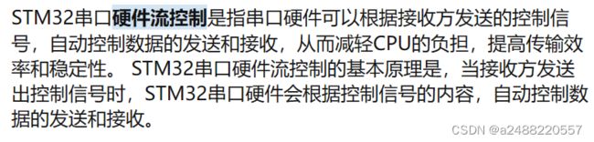
一下是关于USART有关的函数:
1.USART_Init——初始化
typedef struct
{
  uint32_t USART_BaudRate;            /*!< This member configures the USART communication baud rate.
                                           The baud rate is computed using the following formula:
                                            - IntegerDivider = ((PCLKx) / (16 * (USART_InitStruct->USART_BaudRate)))
                                            - FractionalDivider = ((IntegerDivider - ((u32) IntegerDivider)) * 16) + 0.5 */

  uint16_t USART_WordLength;          /*!< Specifies the number of data bits transmitted or received in a frame.
                                           This parameter can be a value of @ref USART_Word_Length */

  uint16_t USART_StopBits;            /*!< Specifies the number of stop bits transmitted.
                                           This parameter can be a value of @ref USART_Stop_Bits */

  uint16_t USART_Parity;              /*!< Specifies the parity mode.
                                           This parameter can be a value of @ref USART_Parity
                                           @note When parity is enabled, the computed parity is inserted
                                                 at the MSB position of the transmitted data (9th bit when
                                                 the word length is set to 9 data bits; 8th bit when the
                                                 word length is set to 8 data bits). */

  uint16_t USART_Mode;                /*!< Specifies wether the Receive or Transmit mode is enabled or disabled.
                                           This parameter can be a value of @ref USART_Mode */

  uint16_t USART_HardwareFlowControl; /*!< Specifies wether the hardware flow control mode is enabled
                                           or disabled.
                                           This parameter can be a value of @ref USART_Hardware_Flow_Control */
} USART_InitTypeDef;
USART_BaudRate——波特率
USART_WordLength——字节我们选择8位
USART_StopBits——停止位,我们选择一位,这样满足8位
USART_Parity——有无校验,我们无
USART_Mode——TX和RX我们可以选择,RX(我们只读)
USART_HardwareFlowControl——硬件流控(上面有有关解释)
USART总结一下:
先要理解一下总线:
(1)芯片总线:连接各个模块。用于各个模块的通信
(2)系统总线(内总线):I2C,I2C需要外设,微控制器系统或智能仪器内部各模块,各器件之间传送信息的通道。
(3)通信总线:(外总线),两个或多个系统之间的通信。
数据帧:信号传输时:有起始位,数据位,ji偶位,停止位。
波特率:异步通信要有相同的波特率,比特率越高,传输速度越快。
在32中,USART有五个串行通信接口,USART1在APB2总线中是72MHZ,其他在APB1中线中是36MHZ。
void USART_DeInit(USART_TypeDef* USARTx);
//USART初始化:根据USART初始化结构参数USART外设
void USART_Init(USART_TypeDef* USARTx, USART_InitTypeDef* USART_InitStruct);
//USART解除初始化//
void USART_StructInit(USART_InitTypeDef* USART_InitStruct);
//使用默认值填充USART初始化结构体成员
void USART_Cmd(USART_TypeDef* USARTx, FunctionalState NewState);
//允许或禁止USART外设
uint16_t USART_ReceiveData(USART_TypeDef* USARTx);
//返回USART外设最新接收的数据
void USART_SendData(USART_TypeDef* USARTx, uint16_t Data);
//通过USART外设发送当个数据
void USART_SendBreak(USART_TypeDef* USARTx);
//发送终止字符
void USART_ITConfig(USART_TypeDef* USARTx, uint16_t USART_IT, FunctionalState NewState);
//设置USART的某个中断请求是允许或禁止
ITStatus USART_GetITStatus(USART_TypeDef* USARTx, uint16_t USART_IT);
//获取USART中断状态
void USART_ClearITPendingBit(USART_TypeDef* USARTx, uint16_t USART_IT);
//清除USART某个挂起中断标志
FlagStatus USART_GetFlagStatus(USART_TypeDef* USARTx, uint16_t USART_FLAG);
//获取标志状态:检测某个USART事件是否置位
void USART_ClearFlag(USART_TypeDef* USARTx, uint16_t USART_FLAG);
//挂起标志清除:清除某个USART事件挂起标志
关于中断 NVIC:
    USART_ITConfig(USART1,USART_IT_RXNE,ENABLE);//中断使能
	NVIC_PriorityGroupConfig(NVIC_PriorityGroup_2);//分组(组别)

	NVIC_InitTypeDef NVIC_InitStructure;
	NVIC_InitStructure.NVIC_IRQChannel = USART1_IRQn;//选择USART1中断
	NVIC_InitStructure.NVIC_IRQChannelCmd = ENABLE;//USART1使能
	NVIC_InitStructure.NVIC_IRQChannelPreemptionPriority = 2;//抢占优先级
    NVIC_InitStructure.NVIC_IRQChannelSubPriority = 1;//响应优先级
	NVIC_Init(&NVIC_InitStructure);
组别优先顺序(第0组优先级最强,第4组优先级最弱):NVIC_PriorityGroup_0>NVIC_PriorityGroup_1>NVIC_PriorityGroup_2>NVIC_PriorityGroup_3>NVIC_PriorityGroup_4 。
USART1_IRQHandler——中断函数,
void USART1_IRQHandler()//中断先判断标志位
{
	if(USART_GetFlagStatus(USART1,USART_IT_RXNE)==SET)
	{
		MyserialDate=USART_ReceiveData(USART1);
		MyserialFalg = 1;
		USART_ClearITPendingBit(USART1,USART_IT_RXNE);
	}
}
先判断USART1中断标志位,是否为“1”,如果有把收到了给 一个数据,然后返回。
下来说PWM控制电机,编码器的有关代码。
#include "stm32f10x.h"                  // Device header
void MyMotorPWM_Init()
{
	RCC_APB1PeriphClockCmd(RCC_APB1Periph_TIM2,ENABLE);
	RCC_APB2PeriphClockCmd(RCC_APB2Periph_GPIOA,ENABLE);

	GPIO_InitTypeDef GPIO_InitStructure;
	GPIO_InitStructure.GPIO_Mode = GPIO_Mode_AF_PP;
	GPIO_InitStructure.GPIO_Pin = GPIO_Pin_2|GPIO_Pin_3;
	GPIO_InitStructure.GPIO_Speed = GPIO_Speed_50MHz;
	GPIO_Init(GPIOA,&GPIO_InitStructure);

	TIM_InternalClockConfig(TIM2);//内部时钟

	TIM_TimeBaseInitTypeDef TIM_TimeBaseInitStructure;
	TIM_TimeBaseInitStructure.TIM_ClockDivision =TIM_CKD_DIV1 ;
	TIM_TimeBaseInitStructure.TIM_CounterMode = TIM_CounterMode_Up;
	TIM_TimeBaseInitStructure.TIM_Period = 7200-1;//ARR
	TIM_TimeBaseInitStructure.TIM_Prescaler = 36-1;//PSC
	/*CCR=720=0.1
	      1440=0.2
	*/
	TIM_TimeBaseInitStructure.TIM_RepetitionCounter = 0;
	TIM_TimeBaseInit(TIM2,&TIM_TimeBaseInitStructure);

	TIM_OCInitTypeDef TIM_OCInitStructure;
	TIM_OCStructInit(&TIM_OCInitStructure);
	TIM_OCInitStructure.TIM_OCMode = TIM_OCMode_PWM1;
	TIM_OCInitStructure.TIM_OCPolarity = TIM_OCPolarity_High;
	TIM_OCInitStructure.TIM_OutputState =TIM_OutputState_Enable ;
	TIM_OCInitStructure.TIM_Pulse = 0;//ccr
	TIM_OC3Init(TIM2,&TIM_OCInitStructure);
	TIM_OC4Init(TIM2,&TIM_OCInitStructure);

//	TIM_ClearFlag(TIM2,TIM_FLAG_Update);//更新中断标志位清除,防止复位以后直接进入终端,计数从1开始计数
//
//	TIM_ITConfig(TIM2,TIM_IT_Update,ENABLE);
//
//	NVIC_PriorityGroupConfig(NVIC_PriorityGroup_2);
//
//	NVIC_InitTypeDef NVIC_InitStructure;
//	NVIC_InitStructure.NVIC_IRQChannel = TIM2_IRQn;
//	NVIC_InitStructure.NVIC_IRQChannelCmd = ENABLE;
//	NVIC_InitStructure.NVIC_IRQChannelPreemptionPriority = 2;//抢占优先级
//	NVIC_InitStructure.NVIC_IRQChannelSubPriority = 1;//响应优先级
//  NVIC_Init(&NVIC_InitStructure);
	TIM_SetCompare3(TIM2,7200-0);
	TIM_SetCompare4(TIM2,0);
	TIM_Cmd(TIM2,ENABLE);
}
//改变CCR
void MyPWM_SetCompare3(uint16_t Compare)
{
		TIM_SetCompare3(TIM2,Compare);
}
void MyPWM_SetCompare4(uint16_t Compare)
{
		TIM_SetCompare4(TIM2,Compare);
}
void PWM_Xianfu(int max,int *PWM)
{
	if(*PWM>max)  *PWM = max;
	if(*PWM<-max) *PWM =-max;
}
//===============================电机=================================//
//PA4,5,7,11
void MyMotor_Init()
{
	MyMotorPWM_Init();
	RCC_APB2PeriphClockCmd(RCC_APB2Periph_GPIOA,ENABLE);

	GPIO_InitTypeDef GPIO_InitStructure;
	GPIO_InitStructure.GPIO_Mode = GPIO_Mode_Out_PP;
	GPIO_InitStructure.GPIO_Pin = GPIO_Pin_4|GPIO_Pin_5|GPIO_Pin_1|GPIO_Pin_11;
	GPIO_InitStructure.GPIO_Speed = GPIO_Speed_50MHz;
	GPIO_Init(GPIOA,&GPIO_InitStructure);
}

void MyMotor_SetSpeed(uint16_t Speed)
{
	if(Speed>0)
	{
		GPIO_SetBits(GPIOA,GPIO_Pin_4);
		GPIO_ResetBits(GPIOA,GPIO_Pin_5);//L
		GPIO_SetBits(GPIOA,GPIO_Pin_1);
		GPIO_ResetBits(GPIOA,GPIO_Pin_11);
		MyPWM_SetCompare3(Speed);
		MyPWM_SetCompare4(Speed);
	}
	else
	{
		GPIO_SetBits(GPIOA,GPIO_Pin_5);
		GPIO_ResetBits(GPIOA,GPIO_Pin_4);
		GPIO_SetBits(GPIOA,GPIO_Pin_11);
		GPIO_ResetBits(GPIOA,GPIO_Pin_1);
		MyPWM_SetCompare3(-Speed);
		MyPWM_SetCompare4(-Speed);
	}
}
//====================================编码器RTIM3CH1CH2(PA6,PA7)  TIM4CH1 CH2(PB6,PB7)====================================//
void RMyEncoder_Init()
{
	RCC_APB2PeriphClockCmd(RCC_APB2Periph_GPIOA,ENABLE);
	RCC_APB1PeriphClockCmd(RCC_APB1Periph_TIM3,ENABLE);


	GPIO_InitTypeDef GPIO_InitStructure;
	GPIO_InitStructure.GPIO_Mode = GPIO_Mode_IPU;
	GPIO_InitStructure.GPIO_Pin = GPIO_Pin_6|GPIO_Pin_7;
	GPIO_InitStructure.GPIO_Speed = GPIO_Speed_50MHz;
	GPIO_Init(GPIOA,&GPIO_InitStructure);


	TIM_TimeBaseInitTypeDef TIM_TimeBaseInitStructure;
	TIM_TimeBaseStructInit(&TIM_TimeBaseInitStructure);
	TIM_TimeBaseInitStructure.TIM_ClockDivision = TIM_CKD_DIV1;
	TIM_TimeBaseInitStructure.TIM_CounterMode = TIM_CounterMode_Up;
	TIM_TimeBaseInitStructure.TIM_Period = 65535-1;//ARR
	TIM_TimeBaseInitStructure.TIM_Prescaler = 1-1;//PSC
	TIM_TimeBaseInitStructure.TIM_RepetitionCounter = 0;
	TIM_TimeBaseInit(TIM3,&TIM_TimeBaseInitStructure);

	TIM_ICInitTypeDef TIM_ICInitStructure;
	TIM_ICStructInit(&TIM_ICInitStructure);
	TIM_ICInitStructure.TIM_Channel = TIM_Channel_1;
	TIM_ICInitStructure.TIM_ICFilter = 0xF;
	//TIM_ICInitStructure.TIM_ICPolarity = TIM_ICPolarity_Falling;
	TIM_ICInit(TIM3,&TIM_ICInitStructure);
	TIM_ICInitStructure.TIM_Channel = TIM_Channel_2;
	TIM_ICInitStructure.TIM_ICFilter = 0xF;
	//TIM_ICInitStructure.TIM_ICPolarity = TIM_ICPolarity_Falling;
	TIM_ICInit(TIM3,&TIM_ICInitStructure);
	TIM_EncoderInterfaceConfig(TIM3,TIM_EncoderMode_TI12,TIM_ICPolarity_Rising,TIM_ICPolarity_Rising);//编码结构
//	TIM_SetCounter(TIM3,0);//清零定时器计数值
//	TIM_SetCounter(TIM4,0);//清零定时器计数值
	TIM_Cmd(TIM3,ENABLE);


}

void LMyEncoder_Init()
{
	RCC_APB2PeriphClockCmd(RCC_APB2Periph_GPIOB,ENABLE);
	RCC_APB1PeriphClockCmd(RCC_APB1Periph_TIM4,ENABLE);


	GPIO_InitTypeDef GPIO_InitStructure;
	GPIO_InitStructure.GPIO_Mode = GPIO_Mode_IPU;
	GPIO_InitStructure.GPIO_Pin = GPIO_Pin_6|GPIO_Pin_7;
	GPIO_InitStructure.GPIO_Speed = GPIO_Speed_50MHz;
	GPIO_Init(GPIOB,&GPIO_InitStructure);


	TIM_TimeBaseInitTypeDef TIM_TimeBaseInitStructure;
	TIM_TimeBaseStructInit(&TIM_TimeBaseInitStructure);
	TIM_TimeBaseInitStructure.TIM_ClockDivision = TIM_CKD_DIV1;
	TIM_TimeBaseInitStructure.TIM_CounterMode = TIM_CounterMode_Up;
	TIM_TimeBaseInitStructure.TIM_Period = 65535-1;//ARR
	TIM_TimeBaseInitStructure.TIM_Prescaler = 1-1;//PSC
	TIM_TimeBaseInitStructure.TIM_RepetitionCounter = 0;
	TIM_TimeBaseInit(TIM4,&TIM_TimeBaseInitStructure);

	TIM_ICInitTypeDef TIM_ICInitStructure;
	TIM_ICStructInit(&TIM_ICInitStructure);
	TIM_ICInitStructure.TIM_Channel = TIM_Channel_1;
	TIM_ICInitStructure.TIM_ICFilter = 0xF;
	//TIM_ICInitStructure.TIM_ICPolarity = TIM_ICPolarity_Falling;
	TIM_ICInit(TIM4,&TIM_ICInitStructure);
	TIM_ICInitStructure.TIM_Channel = TIM_Channel_2;
	TIM_ICInitStructure.TIM_ICFilter = 0xF;
	//TIM_ICInitStructure.TIM_ICPolarity = TIM_ICPolarity_Falling;
	TIM_ICInit(TIM4,&TIM_ICInitStructure);
	TIM_EncoderInterfaceConfig(TIM4,TIM_EncoderMode_TI12,TIM_ICPolarity_Rising,TIM_ICPolarity_Rising);//编码结构

	TIM_Cmd(TIM4,ENABLE);
}


int16_t REncoder_Get()
{
	int16_t MyCnt;
	MyCnt=(short)TIM_GetCounter(TIM3);
	TIM_SetCounter(TIM3,0);
	return MyCnt;
}

int16_t LEncoder_Get()
{
	int16_t MyCnt;
	MyCnt=(short)TIM_GetCounter(TIM4);
	TIM_SetCounter(TIM4,0);
	return MyCnt;
}
//=======================================正反转==================//

void left_positive(void) //左轮正传
{
	GPIO_SetBits(GPIOA,GPIO_Pin_1);
	GPIO_ResetBits(GPIOA,GPIO_Pin_11);
}

void left_negative(void) //左轮反转
{
	GPIO_SetBits(GPIOA,GPIO_Pin_11);
	GPIO_ResetBits(GPIOA,GPIO_Pin_1);
}

void right_positive(void) //右轮正转
{
	GPIO_SetBits(GPIOA,GPIO_Pin_4);
	GPIO_ResetBits(GPIOA,GPIO_Pin_5);

}

void right_negative(void) //右轮反转
{
	GPIO_SetBits(GPIOA,GPIO_Pin_5);
	GPIO_ResetBits(GPIOA,GPIO_Pin_4);
}
//================================//
void left_zhuan()
{
	left_negative();
	right_positive();
	MyPWM_SetCompare3(1440);
	MyPWM_SetCompare4(1440);

}
void right_zhuan()
{
	right_negative();
	left_positive();
	MyPWM_SetCompare3(20);
	MyPWM_SetCompare4(20);

}

void SETPWM(int PWM)
{
	if(PWM>0) //正转
	{
		left_positive();
		right_positive();
		MyPWM_SetCompare3(PWM);
		MyPWM_SetCompare4(PWM);
	}
	else      //反转
	{
		left_negative();
		right_negative();
		MyPWM_SetCompare3(-PWM);
		MyPWM_SetCompare4(-PWM );
	}
}
先说PWM的代码:
配置TIM2,和TIM2,OC
计算
TIM_InternalClockConfig(TIM2);//内部时钟
	TIM_OCInitTypeDef TIM_OCInitStructure;
	TIM_OCStructInit(&TIM_OCInitStructure);
	TIM_OCInitStructure.TIM_OCMode = TIM_OCMode_PWM1;
	TIM_OCInitStructure.TIM_OCPolarity = TIM_OCPolarity_High;
	TIM_OCInitStructure.TIM_OutputState =TIM_OutputState_Enable ;//用于设置定时器输出通道的使能状态
	TIM_OCInitStructure.TIM_Pulse = 0;//ccr
	TIM_OC3Init(TIM2,&TIM_OCInitStructure);
	TIM_OC4Init(TIM2,&TIM_OCInitStructure);

	TIM_SetCompare3(TIM2,7200-0);//写入ccr
	TIM_SetCompare4(TIM2,0);//写入ccr
TIM_Cmd(TIM2,ENABLE); 
这里的限幅为了防止电机烧坏。有pwm限幅
反转GPIO口来,控制正反转,写入ccr的值,来控制PWM,电机转动。
下来是编码器:
利用输入捕获,只可以用到定时器CH1和CH2通道。
int16_t REncoder_Get()
{
	int16_t MyCnt;
	MyCnt=(short)TIM_GetCounter(TIM3);
	TIM_SetCounter(TIM3,0);
	return MyCnt;
}

int16_t LEncoder_Get()
{
	int16_t MyCnt;
	MyCnt=(short)TIM_GetCounter(TIM4);
	TIM_SetCounter(TIM4,0);
	return MyCnt;
}
电机没啥的,也就是TIM2——PWM输出,TIM3,4——编码器输入捕获。
然后用TIM——GetCount(TIM3) 读取TIMx寄存器CNT中的计数值。
下来说一下PID
if(mpu_dmp_get_data(&pitch,&roll,&yaw)==0)
				{
						measure = pitch;                                     //roll测量值
						calcu = zhongzhi;                                   //roll理论值

						velocity = ( LEncoder_Get() + REncoder_Get() )/2 ; //速度测量值      velocity = ( LEncoder_Get() + REncoder_Get() )/2


						//PID计算:直立环+速度环
						PWM = vertical_PID_value(measure, calcu) + velocity_PID_value(velocity);
						PWM_Xianfu(7000,&PWM);      //PWM限幅

						SETPWM(PWM);
				}
//ֱ//直立环:
int vertical_PID_value(float measure,float calcu)
{
err = measure - calcu; //误差
err_sum+=err; //误差的累加
err_difference = err - last_err; //误差的差值
last_err = err; //此次误差记录为“上次误差”
return Kp*err + Ki*err_sum + Kd*err_difference;
}
//速度环:
int velocity_PID_value(int velocity)
{
float a=0.3; //滤波系数(反映滤波程度)
filt_velocity = a*velocity + (1-a)*last_filt_velocity; //一阶速度滤波
velocity_sum += filt_velocity; //速度的累加
I_xianfu(10000); //累加限幅
last_filt_velocity = filt_velocity; //此次速度记录为“上次速度”
return VKp*filt_velocity + VKi*velocity_sum;
}
//I限幅:
void I_xianfu(int max)
{
if(velocity_sum>max) velocity_sum=max;
if(velocity_sum<-max) velocity_sum=-max;
}这里直立环P,是让小车,可以接近要求速度,但是因为会有摩擦力影响(Kp*误差),i是误差累计
上次误差加这一次的误差*Ki。D是让小车这次和上次的误差,所以说是一个负数。减小 小车大幅度震荡
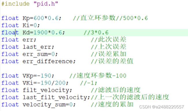
下面是参数