09 AB 10串口通信发送原理
通用异步收发传输器( Universal Asynchronous Receiver/Transmitter, UART)是一种异步收发传输器,其在数据发送时将并行数据转换成串行数据来传输, 在数据接收时将接收到的串行数据转换成并行数据, 可以实现全双工传输和接收。它包括了 RS232、 RS449、 RS423、RS422 和 RS485 等接口标准规范和总线标准规范。 换句话说, UART 是异步串行通信的总称。而 RS232、 RS449、 RS423、 RS422 和 RS485 等,是对应各种异步串行通信口的接口标准和总线标准,它们规定了通信口的电气特性、传输速率、连接特性和接口的机械特性等内容。
1. 09AB 基于FPGA的串口(UART)发送实验
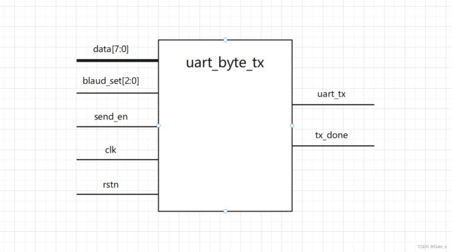
- 串口通信模块设计的目的是用来发送数据的,因此需要有一个数据输入端口。
- 串口通信,支持不同的波特率,所以需要有一个波特率设置端口。
- 串口通信的本质就是将8位的并行数据,在不同的时刻传输并行数据的不同位,通过一根信号线将八位并行数据全部传出。
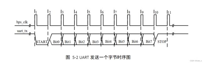
- 串口通信以1位的低电平标志串行传输的开始,待8位数据传输完成之后,再以1位的高电平标志传输的结束。
- 控制信号,控制并转串模块什么时候开始工作,什么时候一个数据发送完成?所以需要一个发送开始信号,以及一个发送完成信号
设计代码
- bps_cnt在空闲状态下保持为0,而bps_cnt为0会使得uart_tx为0,为了解决该问题,我们避开空闲状态下的bps_cnt=0,使bps_cnt从1开始判定。
- 但是这又会导致bps_cnt从0到1存在空闲,发送起始位时会延后一段数据位,于是我们将基础计数时间改为1时counter1开始加一。
- 为了出现bps_clk脉冲信号,当(div_cnt == (bps_dr - 1)成立时会输出1,我们利用该特性作为我们的脉冲信号。
- 我们要输入八位数据以及起始位和终止位共十位数据,为了保证十位数据完整输出,我们需要设置到第十一位停止,发送tx_done信号。
- 输入信号不能是reg类型,否则综合设计代码时报错:Non-net port key_in cannot be of mode input,写代码时遇到的问题。
module uart_byte_tx(
    clk,
    rstn,
    blaud_set,
    data,
    send_en,
    uart_tx,
    tx_done
);

    input clk;
    input rstn;
    input [2:0]blaud_set;
    input [7:0]data;
    input send_en;
    output reg uart_tx;
    output tx_done;

    //Blaud_set = 0时,波特率 = 9600;
    //Blaud_set = 1时,波特率 = 19200;
    //Blaud_set = 2时,波特率 = 38400;
    //Blaud_set = 3时,波特率 = 57600;
    //Blaud_set = 4时,波特率 = 115200;

    reg[17:0] bps_dr;
    always@(*)
        case(blaud_set)
            0: bps_dr = 1000000000/9600/20;
            1: bps_dr = 1000000000/19200/20;
            2: bps_dr = 1000000000/38400/20;
            3: bps_dr = 1000000000/57600/20;
            4: bps_dr = 1000000000/115200/20;
        endcase

    wire bps_clk;
    assign bps_clk = (div_cnt == (bps_dr - 1)); //3.为了出现bps_clk脉冲信号

    reg[17:0] div_cnt;
    always@(posedge clk or negedge rstn)
    if(!rstn)
        div_cnt <= 0;
    else if(send_en)begin
        if(bps_clk)
            div_cnt <= 0;
        else
            div_cnt <= div_cnt + 1'd1;
    end
    else
        div_cnt <= 0;

    reg[3:0] bps_cnt;
    always@(posedge clk or negedge rstn)
    if(!rstn)
        bps_cnt <= 0;
    else if(send_en)begin
        if(bps_cnt == 11)
            bps_cnt <= 0;
        else if(div_cnt == 1) //注意2
            bps_cnt <= bps_cnt + 4'd1;
    end
    else
        bps_cnt <= 0;

    reg tx_done;
    always@(posedge clk or negedge rstn)
    if(!rstn)
        uart_tx <= 1'd1;
    else
        case(bps_cnt)
            1: begin uart_tx <= 1'd0; tx_done <= 0; end //注意1
            2: uart_tx <= data[0];
            3: uart_tx <= data[1];
            4: uart_tx <= data[2];
            5: uart_tx <= data[3];
            6: uart_tx <= data[4];
            7: uart_tx <= data[5];
            8: uart_tx <= data[6];
            9: uart_tx <= data[7];
            10: uart_tx <= 1'd1;
            11: begin uart_tx <= 1'd1; tx_done <= 1; end //注意4
            default: uart_tx <= 1'd1;
        endcase

endmodule
仿真代码:
`timescale 1ns/1ns

module uart_byte_tx_tb();

    reg clk;
    reg rstn;
    reg [2:0] blaud_set;
    reg [7:0] data;
    reg send_en;
    wire uart_tx;
    wire tx_done;

    uart_byte_tx uart_byte_tx_inst(
        .clk(clk),
        .rstn(rstn),
        .blaud_set(blaud_set),
        .data(data),
        .send_en(send_en),
        .uart_tx(uart_tx),
        .tx_done(tx_done)
    );

    initial clk = 1;
    always #10 clk = ~clk;

    initial begin
        rstn = 0;
        data = 0;
        send_en = 0;
        blaud_set = 4;
        #201;
        rstn = 1;
        #100
        data = 8'h57;
        send_en = 1;
        #20;
        @(posedge tx_done);
        send_en = 0;
        #20000;
        data = 8'h75;
        send_en = 1;
        #20;
        @(posedge tx_done);
        #20000;
        send_en = 0;
        $stop;

    end

endmodule
仿真波形

2. 10 串口发送应用之发送数据
使用上一节课设计的串口发送模块,设计一个数据发送器,每10ms以115200的波特率发送一个数据,每次发送的数据比前一个数据大一(计数器)。
在实际应用的时候,我们不能通过counter去控制data,只能通过控制信号去控制。要求就是通过tx_done和send_en这两个控制信号,控制我要发送的数据内容。
思路:通过顶层模块调用uart_byte_tx发送模块来发送数据,将顶层模块命名为uart_tx_test。

设计代码(第一版,不完善)
2.1 直接使用上一节的uart_byte_tx模块:
module uart_tx_test(
    clk,
    rstn,
    uart_tx
);

    input clk;
    input rstn;
    output uart_tx;

    reg [7:0] data;
    reg send_en;
    uart_byte_tx uart_byte_tx_inst(
        .clk(clk),
        .rstn(rstn),
        .blaud_set(3'd4),
        .data(data),
        .send_en(send_en),
        .uart_tx(uart_tx),
        .tx_done(tx_done)
    );

    //10ms周期计数器
    reg [18:0] counter;
    always@(posedge clk or negedge rstn)
    if(!rstn)
        counter <= 0;
    else if(counter == 499999)
        counter <= 0;
    else
        counter <= counter + 1'd1;

    always@(posedge clk or negedge rstn)
    if(!rstn)
        send_en <= 0;
    else if(counter == 0)
        send_en <= 1;
    else if(tx_done)
        send_en <= 0;

    always@(posedge clk or negedge rstn)
    if(!rstn)
        data <= 8'b0000_0000;
    else if(tx_done)
        data <= data + 1'd1;


endmodule
module uart_byte_tx(
    clk,
    rstn,
    blaud_set,
    data,
    send_en,
    uart_tx,
    tx_done
);

    input clk;
    input rstn;
    input [2:0]blaud_set;
    input [7:0]data;
    input send_en;
    output reg uart_tx;
    output tx_done;

    //Blaud_set = 0时,波特率 = 9600;
    //Blaud_set = 1时,波特率 = 19200;
    //Blaud_set = 2时,波特率 = 38400;
    //Blaud_set = 3时,波特率 = 57600;
    //Blaud_set = 4时,波特率 = 115200;

    reg[17:0] bps_dr;
    always@(*)
        case(blaud_set)
            0: bps_dr = 1000000000/9600/20;
            1: bps_dr = 1000000000/19200/20;
            2: bps_dr = 1000000000/38400/20;
            3: bps_dr = 1000000000/57600/20;
            4: bps_dr = 1000000000/115200/20;
        endcase

    wire bps_clk;
    assign bps_clk = (div_cnt == (bps_dr - 1));

    reg[17:0] div_cnt;
    always@(posedge clk or negedge rstn)
    if(!rstn)
        div_cnt <= 0;
    else if(send_en)begin
        if(bps_clk)
            div_cnt <= 0;
        else
            div_cnt <= div_cnt + 1'd1;
    end
    else
        div_cnt <= 0;

    reg[3:0] bps_cnt;
    always@(posedge clk or negedge rstn)
    if(!rstn)
        bps_cnt <= 0;
    else if(send_en)begin
        if(bps_cnt == 11)
            bps_cnt <= 0;
        else if(div_cnt == 1)
            bps_cnt <= bps_cnt + 4'd1;
    end
    else
        bps_cnt <= 0;

    reg tx_done;
    always@(posedge clk or negedge rstn)
    if(!rstn)
        uart_tx <= 1'd1;
    else
        case(bps_cnt) //不完善
            1: begin uart_tx <= 1'd0; tx_done <= 0; end
            2: uart_tx <= data[0];
            3: uart_tx <= data[1];
            4: uart_tx <= data[2];
            5: uart_tx <= data[3];
            6: uart_tx <= data[4];
            7: uart_tx <= data[5];
            8: uart_tx <= data[6];
            9: uart_tx <= data[7];
            10: uart_tx <= 1'd1;
            11: begin uart_tx <= 1'd1; tx_done <= 1; end
            default: uart_tx <= 1'd1;
        endcase

endmodule
仿真代码
`timescale 1ns / 1ps

module uart_tx_test_tb();

    reg clk;
    reg rstn;
    wire uart_tx;

    uart_tx_test uart_tx_test_inst(
        .clk(clk),
        .rstn(rstn),
        .uart_tx(uart_tx)
    );

    initial clk = 1;
    always #10 clk = ~clk;

    initial begin
        rstn = 0;
        #201;
        rstn = 1;
        #200000000
        $stop;
    end

endmodule
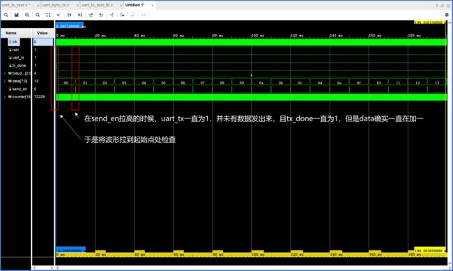
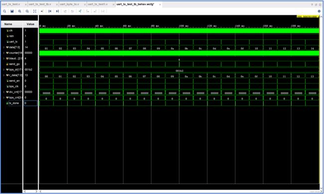
仿真波形
data确实在一直加一,但是data并未发出(uart_tx一直保持为1)

2.2 修改tx_done逻辑后(能运行)
设计代码
module uart_tx_test(
    clk,
    rstn,
    uart_tx
);

    input clk;
    input rstn;
    output uart_tx;

    reg [7:0] data;
    reg send_en;
    uart_byte_tx uart_byte_tx_inst(
        .clk(clk),
        .rstn(rstn),
        .blaud_set(3'd4),
        .data(data),
        .send_en(send_en),
        .uart_tx(uart_tx),
        .tx_done(tx_done)
    );

    //10ms周期计数器
    reg [18:0] counter;
    always@(posedge clk or negedge rstn)
    if(!rstn)
        counter <= 0;
    else if(counter == 499999)
        counter <= 0;
    else
        counter <= counter + 1'd1;

    always@(posedge clk or negedge rstn)
    if(!rstn)
        send_en <= 0;
    else if(counter == 0)
        send_en <= 1;
    else if(tx_done)
        send_en <= 0;

    always@(posedge clk or negedge rstn)
    if(!rstn)
        data <= 8'b0000_0000;
    else if(tx_done)
        data <= data + 1'd1;


endmodule
module uart_byte_tx(
clk,
rstn,
blaud_set,
data,
send_en,
uart_tx,
tx_done
);
input clk;
input rstn;
input [2:0]blaud_set;
input [7:0]data;
input send_en;
output reg uart_tx;
output tx_done;
//Blaud_set = 0时,波特率 = 9600;
//Blaud_set = 1时,波特率 = 19200;
//Blaud_set = 2时,波特率 = 38400;
//Blaud_set = 3时,波特率 = 57600;
//Blaud_set = 4时,波特率 = 115200;
reg[17:0] bps_dr;
always@(*)
case(blaud_set)
0: bps_dr = 1000000000/9600/20;
1: bps_dr = 1000000000/19200/20;
2: bps_dr = 1000000000/38400/20;
3: bps_dr = 1000000000/57600/20;
4: bps_dr = 1000000000/115200/20;
endcase
wire bps_clk;
assign bps_clk = (div_cnt == 1);
reg[17:0] div_cnt;
always@(posedge clk or negedge rstn)
if(!rstn)
div_cnt <= 0;
else if(send_en)begin
if(div_cnt == (bps_dr - 1))
div_cnt <= 0;
else
div_cnt <= div_cnt + 1'd1;
end
else
div_cnt <= 0;
reg[3:0] bps_cnt;
always@(posedge clk or negedge rstn)
if(!rstn)
bps_cnt <= 0;
else if(send_en)begin
if(bps_cnt == 11)
bps_cnt <= 0;
else if(div_cnt == 1)
bps_cnt <= bps_cnt + 4'd1;
end
else
bps_cnt <= 0;
reg tx_done;
always@(posedge clk or negedge rstn)
if(!rstn)
uart_tx <= 1'd1;
else
case(bps_cnt)
0: tx_done <= 0;
1: uart_tx <= 1'd0;
2: uart_tx <= data[0];
3: uart_tx <= data[1];
4: uart_tx <= data[2];
5: uart_tx <= data[3];
6: uart_tx <= data[4];
7: uart_tx <= data[5];
8: uart_tx <= data[6];
9: uart_tx <= data[7];
10: uart_tx <= 1'd1;
11: begin uart_tx <= 1'd1; tx_done <= 1; end
default: uart_tx <= 1'd1;
endcase
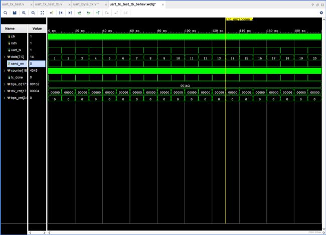
endmodule仿真波形
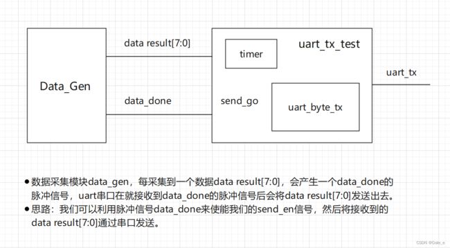
2.3 完善串口模块,使其能接入数据采集模块
- 数据采集模块data_gen,每采集到一个数据data result[7:0],会产生一个data_done的脉冲信号,uart串口在就接收到data_done的脉冲信号后会将data result[7:0]发送出去。
- 思路:我们可以利用脉冲信号data_done来使能我们的send_en信号,然后将接收到的data result[7:0]通过串口发送
- 为了模拟这个过程,我们让顶层uart_tx_test每隔10ms产生一个data[7:0]和一个send_go的单脉冲信号发送给uart_byte_tx模块。让uart_byte_tx模块根据send_go脉冲信号去发数据即可。
- 为了防止数据发送途中data发生变化,我们在接收到send_go信号后,先将data存储起来,即声明一个r_data[7:0],使将data[7:0]的值赋值给r_data[7:0]。
设计代码
module uart_tx_test1(
    clk,
    rstn,
    uart_tx
);

    input clk;
    input rstn;
    output uart_tx;

    reg [7:0] data;
    reg send_go;
    uart_byte_tx uart_byte_tx_inst(
        .clk(clk),
        .rstn(rstn),
        .blaud_set(3'd4),
        .data(data),
        .send_go(send_go),
        .uart_tx(uart_tx),
        .tx_done(tx_done)
    );

    //10ms周期计数器
    reg [18:0] counter;
    always@(posedge clk or negedge rstn)
    if(!rstn)
        counter <= 0;
    else if(counter == 499999)
        counter <= 0;
    else
        counter <= counter + 1'd1;

    always@(posedge clk or negedge rstn)
    if(!rstn)
        send_go <= 0;
    else if(counter == 0)
        send_go <= 1;
    else
        send_go <= 0;

    always@(posedge clk or negedge rstn)
    if(!rstn)
        data <= 8'b0000_0000;
    else if(tx_done)
        data <= data + 1'd1;


endmodule
module uart_byte_tx(
    clk,
    rstn,
    blaud_set,
    data,
    send_go,
    uart_tx,
    tx_done
);

    input clk;
    input rstn;
    input [2:0]blaud_set;
    input [7:0]data;
    input send_go;
    output reg uart_tx;
    output tx_done;

    //Blaud_set = 0时,波特率 = 9600;
    //Blaud_set = 1时,波特率 = 19200;
    //Blaud_set = 2时,波特率 = 38400;
    //Blaud_set = 3时,波特率 = 57600;
    //Blaud_set = 4时,波特率 = 115200;

    reg[17:0] bps_dr;
    always@(*)
        case(blaud_set)
            0: bps_dr = 1000000000/9600/20;
            1: bps_dr = 1000000000/19200/20;
            2: bps_dr = 1000000000/38400/20;
            3: bps_dr = 1000000000/57600/20;
            4: bps_dr = 1000000000/115200/20;
        endcase

    reg [7:0] r_data;
    always@(posedge clk)
    if(send_go)
        r_data <= data;
    else
        r_data <= r_data;

    reg send_en;
    always@(posedge clk or negedge rstn)
    if(!rstn)
        send_en <= 0;
    else if(send_go)
        send_en <= 1;
    else if(tx_done)
        send_en <= 0;


    wire bps_clk;
    assign bps_clk = (div_cnt == 1);
    reg[17:0] div_cnt;
    always@(posedge clk or negedge rstn)
    if(!rstn)
        div_cnt <= 0;
    else if(send_en)begin
        if(div_cnt == (bps_dr - 1))
            div_cnt <= 0;
        else
            div_cnt <= div_cnt + 1'd1;
    end
    else
        div_cnt <= 0;

    reg[3:0] bps_cnt;
    always@(posedge clk or negedge rstn)
    if(!rstn)
        bps_cnt <= 0;
    else if(send_en)begin
        if(bps_cnt == 11)
            bps_cnt <= 0;
        else if(div_cnt == 1)
            bps_cnt <= bps_cnt + 4'd1;
    end
    else
        bps_cnt <= 0;

    reg tx_done;
    always@(posedge clk or negedge rstn)
    if(!rstn)
        uart_tx <= 1'd1;
    else
        case(bps_cnt)
            0: tx_done <= 0;
            1: uart_tx <= 1'd0;
            2: uart_tx <= r_data[0];
            3: uart_tx <= r_data[1];
            4: uart_tx <= r_data[2];
            5: uart_tx <= r_data[3];
            6: uart_tx <= r_data[4];
            7: uart_tx <= r_data[5];
            8: uart_tx <= r_data[6];
            9: uart_tx <= r_data[7];
            10: uart_tx <= 1'd1;
            11: begin uart_tx <= 1'd1; tx_done <= 1; end
            default: uart_tx <= 1'd1;
        endcase

endmodule
仿真代码
`timescale 1ns / 1ps

module uart_tx_test_tb();

    reg clk;
    reg rstn;
    wire uart_tx;

    uart_tx_test1 uart_tx_test_inst(
        .clk(clk),
        .rstn(rstn),
        .uart_tx(uart_tx)
    );

    initial clk = 1;
    always #10 clk = ~clk;

    initial begin
        rstn = 0;
        #201;
        rstn = 1;
        #200000000
        $stop;
    end

endmodule
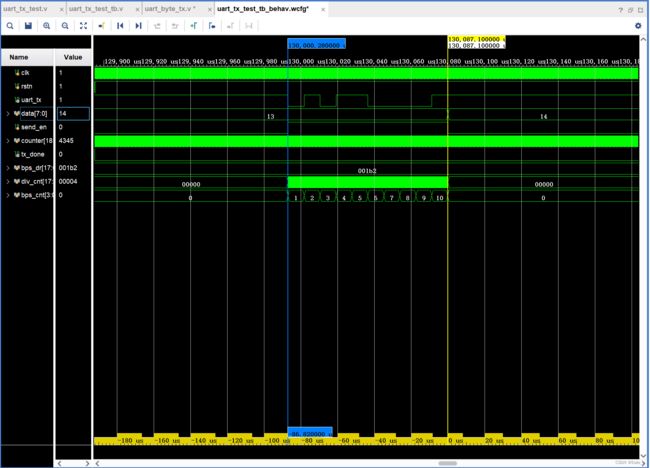
仿真波形
在开发板上跑程序

调试结果:确实按照每100ms法发一个数据
