CCNP课程实验-05-Comprehensive_Experiment
目录
- 实验条件
-
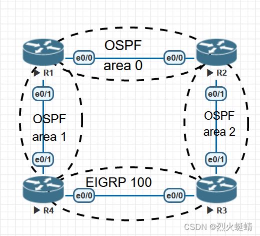
- 网络拓朴
- 基础配置实现
-
- IGP需求:
-
- 1. 根据拓扑所示,配置OSPF和EIGRP
- 2. 在R3上增加一个网段:33.33.33.0/24 (用Loopback 1模拟) 宣告进EIGRP,并在R3上将EIGRP重分布进OSPF。要求重分布进OSPF后的路由Tag值设置为666,且Cost值能沿传递路径累加。但OSPF区域不能出现33.33.33.0/24这条路由。
- 3. 在R1上看到34.1.1.0/24路由的管理距离为111。
- 4. R1和R2之间不需要选举DR、BDR,但需要使用组播更新。
- 5. 在R2上增加两个网段:22.22.1.0/24,22.22.2.0/24 (用Loopback模拟) 视情况宣告进相关区域。在R2上配置最精确的路由汇总,使得R3能看到汇总路由。
- 6. Area 0区域为保证安全,开启区域密文认证,密码为SPOTO
- 7. Area 1区域需尽量减少路由数量,且不允许引入任何外部路由。
- BGP需求
-
- 1. R1和R2采用Loopback 0建立IBGP邻居(AS 12),R3和R4采用Loopback 0建立IBGP邻居(AS 34),R1和R4、R2和R3建立EBGP邻居。
- 2. R1上增加两个网段:10.10.10.0/24,10.10.11.0/24。R2上增加两个网段:20.20.20.0/24,20.20.21.0/24。将这些网段都宣告进BGP。
- 3. 配置使得R3、R4的BGP表如图所示
- IPv6-OSPF需求
-
- 1. 采用OSPFv3方式配置,手动设置Router-id为Loopback 0的IPv4地址,区域设计与IPv4相同。各物理接口都需宣告进OSPF。
- 2. 要求R3能Ping通R4的IPv6 Loopback 0地址。
- IPv6-BGP需求
-
- 1. R1和R2采用Loopback 0建立IBGP邻居,R1和R4、R2和R3建立EBGP邻居。
- 2. R1上增加一个网段:10:10:10::10/128,R3上增加一个网段:30:30:30::30/128 (用Loopback模拟) 并宣告进BGP。要求R1能从10:10:10::10 Ping通R3的30:30:30::30
实验条件
网络拓朴
IPv4:
拓扑中的IPv4互联地址段采用:AB.1.1.X/24,其中AB为两台路由器编号组合。例如:R1-R2之间的AB为12,X为路由器编号,如R1的X=1
Loopback 0接口地址格式为:X.X.X.X/32,其中X为路由器编号。
没有特殊要求,不允许使用静态路由。
IPv6:
拓扑中的IPv6互联地址采用:2001:AB::X/64,其中AB为两台路由器编号组合。例如:R1-R2之间的AB为12,X为路由器编号,如R1的X=1
Loopback 0接口地址格式为:X:X:X::X/128,其中X为路由器编号。
没有特殊要求,不允许使用静态路由。
基础配置实现
R1
R1(config-if)#do show run | s interface
interface Loopback0
 ip address 1.1.1.1 255.255.255.255
interface Ethernet0/0
 ip address 12.1.1.1 255.255.255.0
 no shutdown
interface Ethernet0/1
 ip address 14.1.1.1 255.255.255.0
 no shutdown
R2
R2(config-if)#do show run | s interface
interface Loopback0
 ip address 2.2.2.2 255.255.255.255
interface Ethernet0/0
 ip address 12.1.1.2 255.255.255.0
 no shutdown
interface Ethernet0/1
 ip address 23.1.1.2 255.255.255.0
 no shutdown
R2(config-if)#
R3
R3(config-route-map)#do show run | s interface
interface Loopback0
 ip address 3.3.3.3 255.255.255.255
interface Loopback1
 ip address 33.33.33.33 255.255.255.0
interface Ethernet0/0
 ip address 34.1.1.3 255.255.255.0
 no shutdown
interface Ethernet0/1
 ip address 23.1.1.3 255.255.255.0
 no shutdown
R4
R4(config-router)#do show run | s interface
interface Loopback0
 ip address 4.4.4.4 255.255.255.255
interface Ethernet0/0
 ip address 34.1.1.4 255.255.255.0
 no shutdown
interface Ethernet0/1
 ip address 14.1.1.4 255.255.255.0
 no shutdown
IGP需求:
1. 根据拓扑所示,配置OSPF和EIGRP
R1
router ospf 100
 router-id 1.1.1.1
interface Ethernet0/0
 ip ospf 100 area 0
interface Ethernet0/1
 ip ospf 100 area 1
R2
router ospf 100
 router-id 2.2.2.2
interface Ethernet0/0
 ip ospf 100 area 0
interface Ethernet0/1
 ip ospf 100 area 2
R3
router ospf 100
 router-id 3.3.3.3
interface Ethernet0/1
 ip ospf 100 area 2
router eigrp 100
 network 3.3.3.3 0.0.0.0
 network 34.1.1.3 0.0.0.0
 eigrp router-id 3.3.3.3
R4
router eigrp 100
 network 4.4.4.4 0.0.0.0
 network 34.1.1.4 0.0.0.0
 eigrp router-id 4.4.4.4
router ospf 100
 router-id 4.4.4.4
interface Ethernet0/1
 ip ospf 100 area 1
2. 在R3上增加一个网段:33.33.33.0/24 (用Loopback 1模拟) 宣告进EIGRP,并在R3上将EIGRP重分布进OSPF。要求重分布进OSPF后的路由Tag值设置为666,且Cost值能沿传递路径累加。但OSPF区域不能出现33.33.33.0/24这条路由。
R3
interface Loopback1
 ip address 33.33.33.33 255.255.255.0

ip prefix-list R3-summary seq 5 permit 33.33.33.0/24
route-map R3-summary deny 10
 match ip address prefix-list R3-summary
route-map R3-summary permit 20
 set tag 666
router ospf 100
 redistribute eigrp 100 metric-type 1 subnets route-map R3-summary
3. 在R1上看到34.1.1.0/24路由的管理距离为111。
R1路由表记录
      34.0.0.0/24 is subnetted, 1 subnets
O E1     34.1.1.0 [111/40] via 12.1.1.2, 00:07:21, Ethernet0/0
在router ospf 配置下,使用distance
access-list 10 permit 34.1.1.0 0.0.0.255
router ospf 100
 distance 111 0.0.0.0 255.255.255.255 10
4. R1和R2之间不需要选举DR、BDR,但需要使用组播更新。
把他们的网络类型修改成P2P,就不需要选举DR/BDR了,
R1
interface Ethernet0/0
 ip ospf network point-to-point
R2
interface Ethernet0/0
 ip ospf network point-to-point
5. 在R2上增加两个网段:22.22.1.0/24,22.22.2.0/24 (用Loopback模拟) 视情况宣告进相关区域。在R2上配置最精确的路由汇总,使得R3能看到汇总路由。
R2
interface Loopback0
 ip address 2.2.2.2 255.255.255.255
interface Loopback1
 ip address 22.22.1.1 255.255.255.0

router ospf 100
 network 22.22.1.1 0.0.0.0 area 0
 network 22.22.2.1 0.0.0.0 area 0
 area 0 range 22.22.0.0 255.255.252.0
R3收到了来自2.2.2.2的通告信息
R3#show ip ospf database summary 22.22.0.0

            OSPF Router with ID (3.3.3.3) (Process ID 100)

                Summary Net Link States (Area 2)

  LS age: 1683
  Options: (No TOS-capability, DC, Upward)
  LS Type: Summary Links(Network)
  Link State ID: 22.22.0.0 (summary Network Number)
  Advertising Router: 2.2.2.2
  LS Seq Number: 80000001
  Checksum: 0x20EA
  Length: 28
  Network Mask: /22
        MTID: 0         Metric: 1

R3#
6. Area 0区域为保证安全,开启区域密文认证,密码为SPOTO
R1
interface Ethernet0/0
 ip ospf authentication message-digest
 ip ospf message-digest-key 1 md5 SPOTO
R2
interface Ethernet0/0
 ip ospf authentication message-digest
 ip ospf message-digest-key 1 md5 SPOTO
7. Area 1区域需尽量减少路由数量,且不允许引入任何外部路由。
把Area1区域变成末梢区域,就可以实现目的
R1
router ospf 100
 area 1 stub no-summary
R2
router ospf 100
 area 1 stub
BGP需求
1. R1和R2采用Loopback 0建立IBGP邻居(AS 12),R3和R4采用Loopback 0建立IBGP邻居(AS 34),R1和R4、R2和R3建立EBGP邻居。
R1
router bgp 12
 bgp router-id 1.1.1.1
 bgp log-neighbor-changes
 neighbor 2.2.2.2 remote-as 12
 neighbor 2.2.2.2 update-source Loopback0
 neighbor 2.2.2.2 next-hop-self
 neighbor 14.1.1.4 remote-as 34
R1
router bgp 12
 bgp router-id 2.2.2.2
 bgp log-neighbor-changes
 neighbor 1.1.1.1 remote-as 12
 neighbor 1.1.1.1 update-source Loopback0
 neighbor 1.1.1.1 next-hop-self
 neighbor 23.1.1.3 remote-as 34
R3
router bgp 34
 bgp router-id 3.3.3.3
 bgp log-neighbor-changes
 neighbor 4.4.4.4 remote-as 34
 neighbor 4.4.4.4 update-source Loopback0
 neighbor 4.4.4.4 next-hop-self
 neighbor 23.1.1.2 remote-as 12
R4
router bgp 34
 bgp router-id 4.4.4.4
 bgp log-neighbor-changes
 neighbor 3.3.3.3 remote-as 34
 neighbor 3.3.3.3 update-source Loopback0
 neighbor 3.3.3.3 next-hop-self		// IBGP对等体,最好配置上该项,将路由下跳指向自己
 neighbor 14.1.1.1 remote-as 12
2. R1上增加两个网段:10.10.10.0/24,10.10.11.0/24。R2上增加两个网段:20.20.20.0/24,20.20.21.0/24。将这些网段都宣告进BGP。
R1
interface Loopback1
 ip address 10.10.10.1 255.255.255.0
interface Loopback2
 ip address 10.10.11.1 255.255.255.0

router bgp 12
 network 10.10.10.0 mask 255.255.255.0
 network 10.10.11.0 mask 255.255.255.0
R2
interface Loopback3
 ip address 20.20.20.1 255.255.255.0
interface Loopback4
 ip address 20.20.21.1 255.255.255.0

router bgp 12
 network 20.20.20.0 mask 255.255.255.0
 network 20.20.21.0 mask 255.255.255.0
3. 配置使得R3、R4的BGP表如图所示
R3
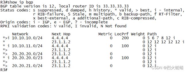
现在的R3BGP路由如下图
     Network          Next Hop            Metric LocPrf Weight Path
 * i  10.10.10.0/24    4.4.4.4                  0    100      0 12 i
 *>                    23.1.1.2                               0 12 i
 * i  10.10.11.0/24    4.4.4.4                  0    100      0 12 i
 *>                    23.1.1.2                               0 12 i
 * i  20.20.20.0/24    4.4.4.4                  0    100      0 12 i
 *>                    23.1.1.2                 0             0 12 i
 * i  20.20.21.0/24    4.4.4.4                  0    100      0 12 i
 *>                    23.1.1.2                 0             0 12 i
R4
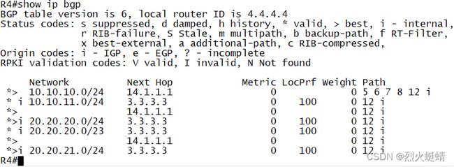
现在的R4BGP路由如下图
     Network          Next Hop            Metric LocPrf Weight Path
 * i  10.10.10.0/24    3.3.3.3                  0    100      0 12 i
 *>                    14.1.1.1                 0             0 12 i
 *>   10.10.11.0/24    14.1.1.1                 0             0 12 i
 * i                   3.3.3.3                  0    100      0 12 i
 *>   20.20.20.0/24    14.1.1.1                               0 12 i
 * i                   3.3.3.3                  0    100      0 12 i
 *>   20.20.21.0/24    14.1.1.1                               0 12 i
 * i                   3.3.3.3                  0    100      0 12 i
比较得出结果
R3:不同点
     Network          Next Hop            Metric LocPrf Weight Path
 * i  10.10.10.0/24    4.4.4.4                  0    100      0 12 i
 *>                    23.1.1.2                               0 12 i
1. 这两条的Path值有改动,从10.10.10.0是EBGP的AS-PATH
2. 下一跳地址为4.4.4.4的路由要成为最优路径,LocalPrf值要设置为200
3. 缺少一条20.20.20.0/23的路由。
1 .先修改R4上通告过来的AS-Path,可以从R1-R4-in 方向进行修改。可以同时修改local-preference值。AS-PATH值只能在EBGP通告的时候,才可以修改, 因此需要在R4上接收的时候,就要修改PATH值,
R4
ip prefix-list bgp seq 5 permit 10.10.10.0/24

route-map R1-R4-in permit 10			// R1-R4-in方向的,进来的10.10.10.0/24路由
 match ip address prefix-list bgp
 set as-path prepend 5 6 7 8			// AS-PATH添加5,6,7,8
route-map R1-R4-in permit 20

// R4-R3-out方向的,出去的10.10.10.0/24路由,
// 要在相同的AS区域内,报文才可以传递PATH-Attribute属性,Local-preference, 也可以在R3上配置,R4-R3-in方向进行修改。
route-map R4-R3-out permit 10
 match ip address prefix-list bgp
 set local-preference 200
route-map R4-R3-out permit 20

router bgp 34
 neighbor 14.1.1.1 route-map R1-R4-in in
 neighbor 3.3.3.3  route-map R4-R3-out out
R4 BGP路由表结果展示
可见PATH值已修改。
R4(config-router)#do show ip bgp
BGP table version is 27, local router ID is 4.4.4.4
Status codes: s suppressed, d damped, h history, * valid, > best, i - internal,
              r RIB-failure, S Stale, m multipath, b backup-path, f RT-Filter,
              x best-external, a additional-path, c RIB-compressed,
              t secondary path,
Origin codes: i - IGP, e - EGP, ? - incomplete
RPKI validation codes: V valid, I invalid, N Not found

     Network          Next Hop            Metric LocPrf Weight Path
 *>   10.10.10.0/24    14.1.1.1                 0             0 5 6 7 8 12 i
 *>   10.10.11.0/24    14.1.1.1                 0             0 12 i
 * i                   3.3.3.3                  0    100      0 12 i
 *>   20.20.20.0/24    14.1.1.1                               0 12 i
 * i                   3.3.3.3                  0    100      0 12 i
 *>   20.20.21.0/24    14.1.1.1                               0 12 i
 * i                   3.3.3.3                  0    100      0 12 i
R3 BGP路由表结果展示
可见PATH值、LocalPrf值都已修改,虽然AS-PATH变长(越短优先),但是因为localprf值越大越优先。所以4.4.4.4这一条的10.10.10.0路由成为最优路径。
R3(config-router)#do show ip bgp
BGP table version is 21, local router ID is 3.3.3.3
Status codes: s suppressed, d damped, h history, * valid, > best, i - internal,
              r RIB-failure, S Stale, m multipath, b backup-path, f RT-Filter,
              x best-external, a additional-path, c RIB-compressed,
              t secondary path,
Origin codes: i - IGP, e - EGP, ? - incomplete
RPKI validation codes: V valid, I invalid, N Not found

     Network          Next Hop            Metric LocPrf Weight Path
 *>i  10.10.10.0/24    4.4.4.4                  0    200      0 5 6 7 8 12 i
 *                     23.1.1.2                               0 12 i
 * i  10.10.11.0/24    4.4.4.4                  0    100      0 12 i
 *>                    23.1.1.2                               0 12 i
 * i  20.20.20.0/24    4.4.4.4                  0    100      0 12 i
 *>                    23.1.1.2                 0             0 12 i
 * i  20.20.21.0/24    4.4.4.4                  0    100      0 12 i
 *>                    23.1.1.2                 0             0 12 i
- 修改23.1.1.2通告过来的路由的AS-PATH值。
在R3上配置, R2-R3-in方向进行配置AS-PATH,因为R2-R3之间是EBGP,所以可以修改AS-PATH
R3
ip prefix-list bgp10 seq 5 permit 10.10.10.0/24

// R2-R3-in方向的,进来的10.10.10.0/24路由
route-map R2-R3-in permit 10
 match ip address prefix-list bgp10
 set as-path prepend last-as 4	// AS-PATH,重复最后一个AS号
route-map R2-R3-in permit 20

router bgp 34
 neighbor 23.1.1.2 route-map R2-R3-in in
R3 BGP路由表结果展示
可见PATH值已修改。
R3(config-router)#do show ip bgp
BGP table version is 21, local router ID is 3.3.3.3
Status codes: s suppressed, d damped, h history, * valid, > best, i - internal,
              r RIB-failure, S Stale, m multipath, b backup-path, f RT-Filter,
              x best-external, a additional-path, c RIB-compressed,
              t secondary path,
Origin codes: i - IGP, e - EGP, ? - incomplete
RPKI validation codes: V valid, I invalid, N Not found

     Network          Next Hop            Metric LocPrf Weight Path
 *>i  10.10.10.0/24    4.4.4.4                  0    200      0 5 6 7 8 12 i
 *                     23.1.1.2                               0 12 12 12 12 12 i
 * i  10.10.11.0/24    4.4.4.4                  0    100      0 12 i
 *>                    23.1.1.2                               0 12 i
 * i  20.20.20.0/24    4.4.4.4                  0    100      0 12 i
 *>                    23.1.1.2                 0             0 12 i
 * i  20.20.21.0/24    4.4.4.4                  0    100      0 12 i
 *>                    23.1.1.2                 0             0 12 i
R4 BGP路由表结果展示
然而R4上并没有收到来自3.3.3.3的,关于10.10.10.0,AS-PATH是12 12 12 12 12 i的记录, 这是因为在R3上,这条记录他不是Best,所以不会被转发给其它IBGP
R4(config-router)#do show ip bgp
BGP table version is 27, local router ID is 4.4.4.4
Status codes: s suppressed, d damped, h history, * valid, > best, i - internal,
              r RIB-failure, S Stale, m multipath, b backup-path, f RT-Filter,
              x best-external, a additional-path, c RIB-compressed,
              t secondary path,
Origin codes: i - IGP, e - EGP, ? - incomplete
RPKI validation codes: V valid, I invalid, N Not found

     Network          Next Hop            Metric LocPrf Weight Path
 *>   10.10.10.0/24    14.1.1.1                 0             0 5 6 7 8 12 i
 *>   10.10.11.0/24    14.1.1.1                 0             0 12 i
 * i                   3.3.3.3                  0    100      0 12 i
 *>   20.20.20.0/24    14.1.1.1                               0 12 i
 * i                   3.3.3.3                  0    100      0 12 i
 *>   20.20.21.0/24    14.1.1.1                               0 12 i
 * i                   3.3.3.3                  0    100      0 12 i
- 缺少了20.20.20.0/23路由记录,要添加这条路由信息
这条记录子网掩码比较短,因此是经过聚合的,综合分析R3,R4图片中的路由信息可得到。 R3有收到R4的聚合路由通告信息。而从R2收到的路由是24位子网掩码的。因此,聚合路由的是R1路由器。且在R4路由器上并没有收到来自R1的24长度的路由,所以可以确定聚合时,只通告汇总路由,不通告明细路由
所以在R1配置如下
router bgp 12
 aggregate-address 20.20.20.0 255.255.254.0 as-set summary-only // summary-only 只通告汇总路由
R3 BGP路由表结果展示
达成图片所要求的路由表效果
R3(config-router)#do show ip bgp
BGP table version is 34, local router ID is 3.3.3.3
Status codes: s suppressed, d damped, h history, * valid, > best, i - internal,
              r RIB-failure, S Stale, m multipath, b backup-path, f RT-Filter,
              x best-external, a additional-path, c RIB-compressed,
              t secondary path,
Origin codes: i - IGP, e - EGP, ? - incomplete
RPKI validation codes: V valid, I invalid, N Not found

     Network          Next Hop            Metric LocPrf Weight Path
 *>i  10.10.10.0/24    4.4.4.4                  0    200      0 5 6 7 8 12 i
 *                     23.1.1.2                               0 12 12 12 12 12 i
 * i  10.10.11.0/24    4.4.4.4                  0    100      0 12 i
 *>                    23.1.1.2                               0 12 i
 *>   20.20.20.0/24    23.1.1.2                 0             0 12 i	// R2通告而来
 * i  20.20.20.0/23    4.4.4.4                  0    100      0 12 i	// R3只通告汇总路由。并且长度24的明细路由
 *>                    23.1.1.2                               0 12 i
 *>   20.20.21.0/24    23.1.1.2                 0             0 12 i
R4 BGP路由表结果展示
达成图片所要求的路由表效果
R4(config-router)#do show ip bgp
BGP table version is 30, local router ID is 4.4.4.4
Status codes: s suppressed, d damped, h history, * valid, > best, i - internal,
              r RIB-failure, S Stale, m multipath, b backup-path, f RT-Filter,
              x best-external, a additional-path, c RIB-compressed,
              t secondary path,
Origin codes: i - IGP, e - EGP, ? - incomplete
RPKI validation codes: V valid, I invalid, N Not found

     Network          Next Hop            Metric LocPrf Weight Path
 *>   10.10.10.0/24    14.1.1.1                 0             0 5 6 7 8 12 i
 *>   10.10.11.0/24    14.1.1.1                 0             0 12 i
 * i                   3.3.3.3                  0    100      0 12 i
 *>i  20.20.20.0/24    3.3.3.3                  0    100      0 12 i	// R3通告而来
 * i  20.20.20.0/23    3.3.3.3                  0    100      0 12 i	// R3通告(adv-router为1.1.1.1的汇总路由)和R2的24长度的路由
 *>                    14.1.1.1                 0             0 12 i	// R1只通告汇总路由
 *>i  20.20.21.0/24    3.3.3.3                  0    100      0 12 i
IPv6-OSPF需求
1. 采用OSPFv3方式配置,手动设置Router-id为Loopback 0的IPv4地址,区域设计与IPv4相同。各物理接口都需宣告进OSPF。
2. 要求R3能Ping通R4的IPv6 Loopback 0地址。
R1
interface Loopback0
 ipv6 address 1:1:1:1::1/128
 ipv6 enable
 ospfv3 100 ipv6 area 0
interface Ethernet0/0
 ipv6 address 2001:12::1/64
 ipv6 enable
 ipv6 ospf 100 area 0
interface Ethernet0/1
 ipv6 address 2001:14::1/64
 ipv6 enable
 ospfv3 100 ipv6 area 1

router ospfv3 100
 router-id 1.1.1.1
 !
 address-family ipv6 unicast
 exit-address-family
R2
R2(config-if)#do show run | s interface
interface Loopback0
 ipv6 address 2:2:2:2::2/128
 ipv6 enable
 ospfv3 100 ipv6 area 0
interface Ethernet0/0
 ipv6 address 2001:12::2/64
 ipv6 enable
 ospfv3 100 ipv6 area 0
interface Ethernet0/1
 ipv6 address 2001:23::2/64
 ipv6 enable
 ospfv3 100 ipv6 area 2

router ospfv3 100
 router-id 2.2.2.2
 !
 address-family ipv6 unicast
 exit-address-family
R3
interface Loopback0
 ipv6 address 3:3:3:3::3/128
 ipv6 enable
 ospfv3 100 ipv6 area 2
interface Ethernet0/0
 ipv6 address 2001:34::3/64
 ipv6 enable
interface Ethernet0/1
 ipv6 address 2001:23::3/64
 ipv6 enable
 ospfv3 100 ipv6 area 2
R4
interface Loopback0
 ipv6 address 4:4:4:4::4/128
 ipv6 enable
 ospfv3 100 ipv6 area 1
interface Ethernet0/1
 ipv6 address 2001:14::4/64
 ipv6 enable
 ospfv3 100 ipv6 area 1

router ospfv3 100
 router-id 4.4.4.4
 !
 address-family ipv6 unicast
 exit-address-family
OSPFv3配置完成之后,R4和R3之间不能直接通信
由R1,R2,R3绕着走。
R4#traceroute 3:3:3:3::3
Type escape sequence to abort.
Tracing the route to 3:3:3:3::3

  1 2001:14::1 1 msec 0 msec 0 msec
  2 2001:12::2 1 msec 0 msec 1 msec
  3 2001:23::3 0 msec 1 msec 0 msec
R4#
测试路由
R3#ping 4:4:4:4::4
Type escape sequence to abort.
Sending 5, 100-byte ICMP Echos to 4:4:4:4::4, timeout is 2 seconds:
!!!!!
Success rate is 100 percent (5/5), round-trip min/avg/max = 1/1/1 ms
R3#
IPv6-BGP需求
1. R1和R2采用Loopback 0建立IBGP邻居,R1和R4、R2和R3建立EBGP邻居。
R1 & R2IBGP邻居
R1#
router bgp 12
 no bgp default ipv4-unicast
 neighbor 2:2:2:2::2 remote-as 12
 neighbor 2:2:2:2::2 update-source Loopback0
 neighbor 2001:14::4 remote-as 34	//R4的EBGP邻居
 !
 address-family ipv6
  neighbor 2:2:2:2::2 activate
  neighbor 2:2:2:2::2 next-hop-self
  neighbor 2001:14::4 activate
 exit-address-family
R2#
router bgp 12
 no bgp default ipv4-unicast
 neighbor 1:1:1:1::1 remote-as 12
 neighbor 1:1:1:1::1 update-source Loopback0
 neighbor 2001:23::3 remote-as 34	//R3的EBGP邻居
 !
 address-family ipv6
  neighbor 1:1:1:1::1 activate
  neighbor 1:1:1:1::1 next-hop-self
  neighbor 2001:23::3 activate
 exit-address-family
R1&R4 EBGP邻居
R4#
router bgp 34
 bgp router-id 4.4.4.4
 bgp log-neighbor-changes
 neighbor 2001:14::1 remote-as 12	//R1的EBGP邻居
 !
 address-family ipv6
  neighbor 2001:14::1 activate
 exit-address-family
R2&R3 EBGP邻居
R3#
router bgp 34
 bgp router-id 3.3.3.3
 bgp log-neighbor-changes
 neighbor 2001:23::2 remote-as 12	//R2的EBGP邻居
 !
 address-family ipv6
  neighbor 2001:23::2 activate
 exit-address-family
IPv6的R3和R4之间并没有IBGP邻居关系
由于OSPFv3路由没有R4-R3之间的直连路由。如果此时在R3和R4之间建立直连路由时。 从R1访问R3时根据BGP选路规则时,选择从R1走到R4时再走到R3时,就有可能发生以下情况。如R1走到R4之后再往下走的时候,由于R4访问R3是通过OSPFv3的选路R4->R1->R2->R3,那么这个时候包又从R4回到R1然后又到R4,就形成了环路
R1#traceroute 30:30:30::30
Type escape sequence to abort.
Tracing the route to 30:30:30::30

  1 2001:14::4 1 msec 0 msec 0 msec
  2 2001:14::1 1 msec 0 msec 0 msec
  3 2001:14::4 0 msec 1 msec *
  4 2001:14::1 1 msec 1 msec 0 msec
  5 2001:14::4 0 msec *  1 msec
  6 2001:14::1 1 msec 1 msec *
  7 2001:14::4 1 msec 0 msec *
  8 2001:14::1 2 msec 0 msec *
  9 2001:14::4 2 msec 1 msec *
 10 2001:14::1 1 msec 1 msec *
 11 2001:14::4 1 msec *  1 msec
 12  *
    2001:14::1 1 msec *
 13 2001:14::4 1 msec *  1 msec
 14  *
    2001:14::1 1 msec *
 15 2001:14::4 2 msec *  1 msec
 16  *
    2001:14::1 2 msec *
 17 2001:14::4 7 msec *  2 msec
 18  *
    2001:14::1 7 msec *
 19 2001:14::4 2 msec *  6 msec
 20  *
    2001:14::1 3 msec *
 21  *  *  *
 22  *  *  *
R1#show ipv route
2. R1上增加一个网段:10:10:10::10/128,R3上增加一个网段:30:30:30::30/128 (用Loopback模拟) 并宣告进BGP。要求R1能从10:10:10::10 Ping通R3的30:30:30::30
R1
R1#show run | s interface
interface Loopback1
 ipv6 address 10:10:10::10/128

router bgp 12
 !
 address-family ipv6
  network 10:10:10::10/128	//宣告10段的路由
 exit-address-family
R3
R3#show run | s interface
interface Loopback1
 ipv6 address 30:30:30::30/128

router bgp 34
 !
 address-family ipv6
  network 30:30:30::30/128	//宣告30段的路由
 exit-address-family
R1从10:10:10::10 Ping通R3的30:30:30::30
R1#ping 30:30:30::30 source 10:10:10::10
Type escape sequence to abort.
Sending 5, 100-byte ICMP Echos to 30:30:30::30, timeout is 2 seconds:
Packet sent with a source address of 10:10:10::10
!!!!!
Success rate is 100 percent (5/5), round-trip min/avg/max = 1/1/1 ms
R1#