综合实验1
实验目的
·增强分析和配置中小型企业网络的综合能力
实验内容
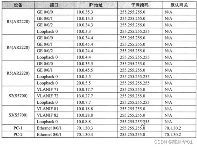
实验拓扑如下所示,实验编址如表8-3所示。本实验模拟了一个企业网络场景, 其中R1和R2为公司总部路由器,交换机S1、S2、S3组成了总部的园区网,R3、R4、 R5为公司分部的路由器。 总部园区网中3台交换机都运行MSTP协议,用来防止二层冗余网络中的环路以及实现 不同VLAN间流量的负载分担,同时还配置了MSTP保护功能以提高网络的可靠性和安全性。 R1、R2、S2、S3运行IS-IS路由协议,以实现总部网络的互通。S2和S3使用IS-IS 下发的缺省路由访问总部芝外的网络。另外,为了提高网络的安全性,还需要配置IS-IS 认证功能。 R3、R4、R5运行OSPF路由协议,以实现公司分部网络的互通。总部与分部之间 通过BGP路由协议互通,同时需要通过修改BGP路由的属性来实现流量的负载分担。
实验拓扑

实验所需的loopback接口IP以拓扑图中的为准

 实验步骤
实验步骤
LSA 1 配置
S1 配置

system-view
Enter system view, return user view with Ctrl+Z.
Info: Information center is disabled.
[Huawei]sysname S1

[Huawei]vlan batch 2 3 4 10 20 30
Info: This operation may take a few seconds. Please wait for a moment...done.

为了保证不同交换机上的同一个VLAN的成员之间能够相互通信,需要配置交换机
之间相连的端口为Trunk端口,并允许VLAN2、VLAN3、VLAN 10、VLAN 20、VLAN
30通过。

[S1]interface GigabitEthernet 0/0/1
[S1-GigabitEthernet0/0/1]port link-type trunk
[S1-GigabitEthernet0/0/1]port trunk allow-pass vlan 2 3 10 20 30
[S1-GigabitEthernet0/0/1]interface GigabitEthernet 0/0/2
[S1-GigabitEthernet0/0/2]port link-type trunk
[S1-GigabitEthernet0/0/2]port trunk allow-pass vlan 23 10 20 30
[S1-GigabitEthernet0/0/2]quit

根据公司的网络规划,人事部属于VLAN2,市场部属于VLAN3:PC-1是人事部
的终端,PC-2是市场部的终端。由于人事部和市场部有业务往来,需要进行跨VLAN
通信,所以决定在交换机S1上配置VLAN聚合,这样做的好处是,既可实现VLAN2
和VLAN3之间的通信,又可以节约IP地址资源。
将PC-1添加到VLAN2,PC-2添加到VLAN3。

[S1]interface Ethernet 0/0/1
[S1-Ethernet0/0/1]port link-type access
[S1-Ethernet0/0/1]port default vlan 2
[S1-Ethernet0/0/1]interface Ethernet 0/0/2
[S1-Ethernet0/0/2]port link-type access
[S1-Ethernet0/0/2]port default vlan 3
[S1-Ethernet0/0/2]quit

[S1]vlan 4
[S1-vlan4]aggregate-vlan //将当前VLAN配置为Super-VLAN(VLAN聚合)
[S1-vlan4]access-vlan 2 to 3 //将一组Sub-VLAN加入Super-VLAN中
[S1-vlan4]quit

Proxy ARP也就是代理ARP,当ARP请求是从一台主机发出,用以解析处于同一逻辑三层网络却不在同一物理网段上的另一台主机的硬件地址时,连接它们的具有代理ARP功能的设备就可以应答该请求,使处于不同物理网段的主机可以正常进行通信。

[S1]interface Vlanif 4
[S1-Vlanif4]ip address 70.1.30.2 24
[S1-Vlanif4]arp-proxy inter-sub-vlan-proxy enable //启动VLAN间的Proxy ARP功能
[S1-Vlanif4]quit

3.配置MSTP协议
为了防止网络中的二层环路,同时对不同VLAN间的流量进行负载分担,配置所有
交换机都工作在MSTP模式。

创建MSTP域huawei,其中的实例1包含VLAN2和VLAN3,并以S2为根交换机:
实例2包含VLAN10、VLAN20和VLAN30,并以S3为根交换机,修订版本号都为1。
为了保证交换网络中加入了其他不支持MSTP的交换机后,S2仍为整个生成树的根交换
机,使用命令stp instance 0priority 0配置交换机S2为CIST的总根。

[S1]stp mode mstp //MSTP模式
[S1]stp region-configuration //进入MST域视图
[S1-mst-region]region-name huawei
[S1-mst-region]instance 1 vlan 2 3 //创建实例1
[S1-mst-region]instance 2 vlan 10 20 30
[S1-mst-region]revision-level 1	 //版本1
[S1-mst-region]active region-configuration //激活MSTP域配置
Info: This operation may take a few seconds. Please wait for a moment...done.
[S1-mst-region]quit

为了保证网络的稳定性,确保当由于链路拥塞或者单向链路故障导致交换机收不到
来自上游交换设备的BPDU时,不会产生临时环路,在S1上启用环路保护功能。
STP环路保护功能是生成树协议中的一个增强功能。 启动了环路保护功能后,如果根端口或Alternate端口长时间收不到来自上游设备的BPDU报文,根端口和Alternate端口不会切换到Forwarding状态,从而不会在网络中形成环路

[S1]interface GigabitEthernet 0/0/1
[S1-GigabitEthernet0/0/1]stp loop-protection //启动当前端口的环路保护功能,防止网络中产生环路
[S1-GigabitEthernet0/0/1]interface GigabitEthernet 0/0/2
[S1-GigabitEthernet0/0/2]stp loop-protection
[S1-GigabitEthernet0/0/2]quit

为了加快生成树的收敛速度,配置交换机S1的Ethernet 0/0/1和Ethernet 0/0/2为边
缘端口,并配置保护功能以防止这些端口因收到不合法的BPDU而影响生成树的计算。

[S1]stp bpdu-protection //启用交换模块的BPDU保护功能
[S1]interface Ethernet 0/0/1
[S1-Ethernet0/0/1]stp edged-port enable //将端口配置成边缘端口
[S1-Ethernet0/0/1]interface Ethernet 0/0/2
[S1-Ethernet0/0/2]stp edged-port enable
[S1-Ethernet0/0/2]quit
LSA 2 配置
S2 配置

system-view
Enter system view, return user view with Ctrl+Z.
[Huawei]sysname S2
[S2]undo info-center enable
Info: Information center is disabled.

[S2]interface LoopBack 0
[S2-LoopBack0]ip address 7.7.7.7 32
[S2-LoopBack0]quit

[S2]vlan batch 2 3 4 10 20 30 71 72
Info: This operation may take a few seconds. Please wait for a moment...done.

[S2]interface Vlanif 71
[S2-Vlanif71]ip address 10.0.17.7 24
[S2-Vlanif71]quit

[S2]interface Vlanif 72
[S2-Vlanif72]ip address 10.0.27.7 24
[S2-Vlanif72]quit

为了保证不同交换机上的同一个VLAN的成员之间能够相互通信,需要配置交换机
之间相连的端口为Trunk端口,并允许VLAN2、VLAN3、VLAN10、VLAN20、VLAN
30通过。

[S2]interface GigabitEthernet 0/0/2
[S2-GigabitEthernet0/0/2]port link-type access
[S2-GigabitEthernet0/0/2]port default vlan 71
[S2-GigabitEthernet0/0/2]quit

[S2]interface GigabitEthernet 0/0/4
[S2-GigabitEthernet0/0/4]port link-type access
[S2-GigabitEthernet0/0/4]port default vlan 72
[S2-GigabitEthernet0/0/4]quit

为了保证不同交换机上的同一个VLAN的成员之间能够相互通信,需要配置交换机
之间相连的端口为Trunk端口,并允许VLAN2、VLAN3、VLAN10、VLAN20、VLAN
30通过。

[S2]interface GigabitEthernet 0/0/1
[S2-GigabitEthernet0/0/1]port link-type trunk
[S2-GigabitEthernet0/0/1]port trunk allow-pass vlan 2 3 10 20 30
[S2-GigabitEthernet0/0/1]interface GigabitEthernet 0/0/3
[S2-GigabitEthernet0/0/3]port link-type trunk
[S2-GigabitEthernet0/0/3]port trunk allow-pass vlan 2 3 10 20 30
[S2-GigabitEthernet0/0/3]quit

3.配置MSTP协议
为了防止网络中的二层环路,同时对不同VLAN间的流量进行负载分担,配置所有
交换机都工作在MSTP模式。
创建MSTP域huawei,其中的实例1包含VLAN2和VLAN3,并以S2为根交换机:
实例2包含VLAN10、VLAN20和VLAN30,并以S3为根交换机,修订版本号都为1。
为了保证交换网络中加入了其他不支持MSTP的交换机后,S2仍为整个生成树的根交换
机,使用命令stp instance 0priority 0配置交换机S2为CIST的总根。

[S2]stp mode mstp
[S2]stp region-configuration
[S2-mst-region]region-name huawei
[S2-mst-region]instance 1 vlan 2 3
[S2-mst-region]instance 2 vlan 10 20 30
[S2-mst-region]revision-level 1
[S2-mst-region]active region-configuration
Info: This operation may take a few seconds. Please wait for a moment...done.
[S2-mst-region]quit
[S2]stp instance 1 priority 0  //设STP实例1的优先级为0,优先级数越小,优先级越高
[S2]stp instance 0 priority 0

4.配置IS-IS路由协议
公司总部内R1、R2、S2、S3运行IS-IS路由协议,并且都属于同一个区域,System
ID由Loopback 0接口地址转换而得到。

[S2]isis 1 //中间到中间系统,内部网关协议
[S2-isis-1]network-entity 49.0001.0070.0700.7007.00
[S2-isis-1]quit

[S2]interface Vlanif 71
[S2-Vlanif71]isis enable //启用ISIS路由功能
[S2-Vlanif71]interface Vlanif 72
[S2-Vlanif72]isis enable
[S2-Vlanif72]quit

[S2]interface LoopBack 0
[S2-LoopBack0]isis enable
[S2-LoopBack0]quit

接下来,将S2和S3中VLANIF 10、VLANIF 20、VLANIF 30接口所涉及的用户网
段引进IS-IS中。另外,为了减少路由条目,需要将连续网段的路由进行聚合。
首先配置各VLANIF 接口的IP地址。

[S2]interface Vlanif 10
[S2-Vlanif10]ip address 70.1.10.1 24
[S2-Vlanif10]interface Vlanif 20
[S2-Vlanif20]ip address 70.1.20.1 24
[S2-Vlanif20]interface Vlanif 30
[S2-Vlanif30]ip address 70.1.30.1 24
[S2-Vlanif30]quit

[S2]isis 1
[S2-isis-1]import-route direct
[S2-isis-1]summary 70.1.0.0 255.255.224.0 //将用户网段引入IS-IS中,且对连续网段的路由进行聚合
[S2-isis-1]quit

为了减少LSP数量以优化网络,修改所有IS-IS接口的网络类型为P2P,
这样就不会选举DIS。首先查看以太网接口下选举DIS的情况
在R1的IS-IS链路状态数据库中,存在着DIS产生的LSP。
修改网络类型为P2P,避免选举DIS。

[S2]interface Vlanif 71
[S2-Vlanif71]isis circuit-type p2p //修改网络类型为P2P,避免选举DIS
[S2-Vlanif71]interface Vlanif 72
[S2-Vlanif72]isis circuit-type p2p
[S2-Vlanif72]quit

[S2]isis 1
[S2-isis-1]area-authentication-mode md5 huawei	//为了提高网络安全性,R1、R2、S2、S3均需要相互通过认证后才能交换IS-IS路由信息。配置认证模式为MD5认证,密钥为huawei
[S2-isis-1]quit
LSA 3 配置
S3 配置

system-view
Enter system view, return user view with Ctrl+Z.
[Huawei]sysname S3
[S3]undo info-center enable
Info: Information center is disabled.

[S3]interface LoopBack 0
[S3-LoopBack0]ip address 8.8.8.8 32
[S3-LoopBack0]quit

[S3]vlan batch 2 3 4 10 20 30 81 82
Info: This operation may take a few seconds. Please wait for a moment...done.

[S3]interface Vlanif 81
[S3-Vlanif81]ip address 10.0.18.8 24
[S3-Vlanif81]quit

[S3]interface Vlanif 82
[S3-Vlanif82]ip address 10.0.28.8 24
[S3-Vlanif82]quit

[S3]interface GigabitEthernet 0/0/1
[S3-GigabitEthernet0/0/1]port link-type access
[S3-GigabitEthernet0/0/1]port default vlan 82
[S3-GigabitEthernet0/0/1]quit

[S3]interface GigabitEthernet 0/0/4
[S3-GigabitEthernet0/0/4]port link-type access
[S3-GigabitEthernet0/0/4]port default vlan 81
[S3-GigabitEthernet0/0/4]quit

为了保证不同交换机上的同一个VLAN的成员之间能够相互通信,需要配置交换机
之间相连的端口为Trunk端口,并允许VLAN2、VLAN3、VLAN10、VLAN20、VLAN
30通过。

[S3]interface GigabitEthernet 0/0/2
[S3-GigabitEthernet0/0/2]port link-type trunk
[S3-GigabitEthernet0/0/2]port trunk allow-pass vlan 2 3 10 20 30
[S3-GigabitEthernet0/0/2]interface GigabitEthernet 0/0/3
[S3-GigabitEthernet0/0/3]port link-type trunk
[S3-GigabitEthernet0/0/3]port trunk allow-pass vlan 2 3 10 20 30
[S3-GigabitEthernet0/0/3]quit

3.配置MSTP协议
为了防止网络中的二层环路,同时对不同VLAN间的流量进行负载分担,配置所有
交换机都工作在MSTP模式。
创建MSTP域huawei,其中的实例1包含VLAN2和VLAN3,并以S2为根交换机:
实例2包含VLAN10、VLAN20和VLAN30,并以S3为根交换机,修订版本号都为1。
为了保证交换网络中加入了其他不支持MSTP的交换机后,S2仍为整个生成树的根交换
机,使用命令stp instance 0priority 0配置交换机S2为CIST的总根。

[S3]stp mode mstp
[S3]stp region-configuration
[S3-mst-region]region-name huawei
[S3-mst-region]instance 1 vlan 2 3
[S3-mst-region]instance 2 vlan 10 20 30
[S3-mst-region]revision-level 1
[S3-mst-region]active region-configuration
Info: This operation may take a few seconds. Please wait for a moment...done.
[S3-mst-region]quit
[S3]stp instance 2 priority 0 设STP实例2的优先级为0,优先级越小,优先级越高

4.配置IS-IS路由协议
公司总部内R1、R2、S2、S3运行IS-IS路由协议,并且都属于同一个区域,System
ID由Loopback 0接口地址转换而得到。

[S3]isis 1	//中间到中间系统,内部网关协议
[S3-isis-1]network-entity 49.0001.0080.0800.8008.00
[S3-isis-1]quit

[S3]interface Vlanif 81
[S3-Vlanif81]isis enable //启用ISIS路由功能
[S3-Vlanif81]interface Vlanif 82
[S3-Vlanif82]isis enable
[S3-Vlanif82]quit

[S3]interface LoopBack 0
[S3-LoopBack0]isis enable
[S3-LoopBack0]quit

接下来,将S2和S3中VLANIF 10、VLANIF 20、VLANIF 30接口所涉及的用户网
段引进IS-IS中。另外,为了减少路由条目,需要将连续网段的路由进行聚合。
首先配置各VLANIF 接口的IP地址。

[S3]interface Vlanif 10
[S3-Vlanif10]ip address 80.1.10.1 24
[S3-Vlanif10]interface Vlanif 20
[S3-Vlanif20]ip address 80.1.20.1 24
[S3-Vlanif20]interface Vlanif 30
[S3-Vlanif30]ip address 80.1.30.1 24
[S3-Vlanif30]quit

[S3]isis 1
[S3-isis-1]import-route direct
[S3-isis-1]summary 80.1.0.0 255.255.224.0 //将用户网段引入IS-IS中,且对连续网段的路由进行聚合
[S3-isis-1]quit

接下来,为了减少LSP数量以优化网络,修改所有IS-IS接口的网络类型为P2P,
这样就不会选举DIS。首先查看以太网接口下选举DIS的情况
在S3的IS-IS链路状态数据库中,存在着DIS产生的LSP。
修改网络类型为P2P,避免选举DIS。

[S3]interface Vlanif 81
[S3-Vlanif81]isis circuit-type p2p //修改网络类型为P2P,避免选举DIS
[S3-Vlanif81]interface Vlanif 82
[S3-Vlanif82]isis circuit-type p2p
[S3-Vlanif82]quit

[S3]isis 1
[S3-isis-1]area-authentication-mode md5 huawei //为了提高网络安全性,R1、R2、S2、S3均需要相互通过认证后才能交换IS-IS路由信息。配置认证模式为MD5认证,密钥为huawei
[S3-isis-1]quit
AR1 配置
R1 配置

system-view
Enter system view, return user view with Ctrl+Z.
[Huawei]sysname R1
[R1]undo info-center enable
Info: Information center is disabled.

[R1]interface GigabitEthernet 0/0/0
[R1-GigabitEthernet0/0/0]ip address 10.0.12.1 24
[R1-GigabitEthernet0/0/0]quit

[R1]interface GigabitEthernet 0/0/1
[R1-GigabitEthernet0/0/1]ip address 10.0.13.1 24
[R1-GigabitEthernet0/0/1]interface GigabitEthernet 0/0/2
[R1-GigabitEthernet0/0/2]ip address 10.0.17.1 24
[R1-GigabitEthernet0/0/2]interface GigabitEthernet 4/0/0
[R1-GigabitEthernet4/0/0]ip address 10.0.18.1 24
[R1-GigabitEthernet4/0/0]quit

[R1]interface LoopBack 0
[R1-LoopBack0]ip address 1.1.1.1 32
[R1-LoopBack0]quit

4.配置IS-IS路由协议
公司总部内R1、R2、S2、S3运行IS-IS路由协议,并且都属于同一个区域,System
ID由Loopback 0接口地址转换而得到。

[R1]isis 1 	//中间到中间系统,内部网关协议
[R1-isis-1]network-entity 49.0001.0010.0100.1001.00 //System ID,由loopback 0接口地址转换而得到
[R1-isis-1]quit

[R1]interface GigabitEthernet 0/0/0
[R1-GigabitEthernet0/0/0]isis enable //启用ISIS路由功能
[R1-GigabitEthernet0/0/0]interface GigabitEthernet 0/0/2
[R1-GigabitEthernet0/0/2]isis enable
[R1-GigabitEthernet0/0/2]interface GigabitEthernet 4/0/0
[R1-GigabitEthernet4/0/0]isis enable
[R1-GigabitEthernet4/0/0]quit

[R1]interface LoopBack 0
[R1-LoopBack0]isis enable
[R1-LoopBack0]quit

接下来,为了减少LSP数量以优化网络,修改所有IS-IS接口的网络类型为P2P,
这样就不会选举DIS。首先查看以太网接口下选举DIS的情况
在R1的IS-IS链路状态数据库中,存在着DIS产生的LSP。
修改网络类型为P2P,避免选举DIS。

[R1]interface GigabitEthernet 0/0/0
[R1-GigabitEthernet0/0/0]isis circuit-type p2p  //修改网络类型为P2P,避免选举DIS
[R1-GigabitEthernet0/0/0]interface GigabitEthernet 0/0/2
[R1-GigabitEthernet0/0/2]isis circuit-type p2p
[R1-GigabitEthernet0/0/2]interface GigabitEthernet 4/0/0
[R1-GigabitEthernet4/0/0]isis circuit-type p2p
[R1-GigabitEthernet4/0/0]quit

[R1]isis 1
[R1-isis-1]default-route-advertise 	//为了使S2和S3能够访问外网,需要在路由器R1和R2上配置IS-IS下发缺省路由
[R1-isis-1]quit

[R1]isis 1
[R1-isis-1]area-authentication-mode md5 huawei	//为了提高网络安全性,R1、R2、S2、S3均需要相互通过认证后才能交换IS-IS路由信息。配置认证模式为MD5认证,密钥为huawei
[R1-isis-1]quit

[R1]router id 10.0.1.1 //创建全局router id

Info: Router ID has been modified, please reset the relative protocols manually
to update the Router ID.

6.配置BGP边界网关路由协议
在RI、R2、R3、R4、R5上配置BGP协议。R1与R3、R2与R4采用直连物理接
口建立EBGP邻居关系;R1与R2使用Loopback 0接口建立IBGP邻居关系:R3、R4、
R5之间使用Loopback 0接口建立IBGP邻居关系。配置R1和R2的Router-ID为其
Loopback 0接口的地址。

[R1]bgp 100
[R1-bgp]peer 10.0.13.3 as-number 200 //指定R3 AS200的物理接口邻居
[R1-bgp]peer 2.2.2.2 as-number 100	//指定R2 AS100的loopback接口邻居
[R1-bgp]peer 2.2.2.2 connect-interface LoopBack 0  //指定更新源
[R1-bgp]quit

可以看到,因为Rl和R2上IS-IS路由条目的Cost值不一样,引入BGP时造成了
MED值不一样,最后导致R3会偏好一些来自IBGP的总部路由。管理员希望,R3上所
获得的总部路由全部来自Rl,R4上所获得的总部路由全部来自R2,这样便可以使得从
公司分部去往公司总部的报文不会在公司分部内部弯绕。实现这一需求的方法有很多,

[R1]bgp 100
[R1-bgp]import-route isis 1	//为了将公司总部的路由信息通告给公司分部,在RI和R2上同时将IS-IS的路由信息引进BGP进程
[R1-bgp]quit

[R1]bgp 100
[R1-bgp]import-route isis 1 med 0  //在RI和R2上将IS-IS路由引入BGP时,可以设定MED的值
[R1-bgp]quit

为了防止次优路径和环路的产生,在R1和R2上配置Router-Policy,当Rl和R2
发布缺省路由时加上此Router-Policy作为限制条件

[R1]acl 2001
[R1-acl-basic-2001]rule permit source 10.0.13.0 0
[R1-acl-basic-2001]quit

[R1]route-policy isis permit node 10 //创建名为isis的路由策略
Info: New Sequence of this List.
[R1-route-policy]if-match acl 2001	//创建一个基于ACL的匹配规则

[R1-route-policy]isis 1
[R1-isis-1]default-route-advertise route-policy isis
[R1-isis-1]quit
AR2 配置
R2 配置

system-view
Enter system view, return user view with Ctrl+Z.
[Huawei]sysname R2
[R2]undo info-center enable
Info: Information center is disabled.

[R2]interface GigabitEthernet 0/0/0
[R2-GigabitEthernet0/0/0]ip address 10.0.12.2 24
[R2-GigabitEthernet0/0/0]interface GigabitEthernet 0/0/1
[R2-GigabitEthernet0/0/1]ip address 10.0.28.2 24
[R2-GigabitEthernet0/0/1]quit

[R2]interface GigabitEthernet 0/0/2
[R2-GigabitEthernet0/0/2]ip address 10.0.24.2 24
[R2-GigabitEthernet0/0/2]quit

[R2]interface GigabitEthernet 4/0/0
[R2-GigabitEthernet4/0/0]ip address 10.0.27.2 24
[R2-GigabitEthernet4/0/0]quit

[R2]interface LoopBack 0
[R2-LoopBack0]ip address 2.2.2.2 32
[R2-LoopBack0]quit

4.配置IS-IS路由协议
公司总部内R1、R2、S2、S3运行IS-IS路由协议,并且都属于同一个区域,System
ID由Loopback 0接口地址转换而得到。

[R2]isis 1	//中间到中间系统,内部网关协议
[R2-isis-1]network-entity 49.0001.0020.0200.2002.00
[R2-isis-1]quit

[R2]interface GigabitEthernet 0/0/0
[R2-GigabitEthernet0/0/0]isis enable //启用ISIS路由功能
[R2-GigabitEthernet0/0/0]interface GigabitEthernet 0/0/1
[R2-GigabitEthernet0/0/1]isis enable
[R2-GigabitEthernet0/0/1]interface GigabitEthernet 4/0/0
[R2-GigabitEthernet4/0/0]isis enable
[R2-GigabitEthernet4/0/0]quit

[R2]interface LoopBack 0
[R2-LoopBack0]isis enable
[R2-LoopBack0]quit

接下来,为了减少LSP数量以优化网络,修改所有IS-IS接口的网络类型为P2P,
这样就不会选举DIS。首先查看以太网接口下选举DIS的情况
在R2的IS-IS链路状态数据库中,存在着DIS产生的LSP。
修改网络类型为P2P,避免选举DIS。

[R2]interface GigabitEthernet 0/0/0
[R2-GigabitEthernet0/0/0]isis circuit-type p2p  //修改网络类型为P2P,避免选举DIS
[R2-GigabitEthernet0/0/0]interface GigabitEthernet 0/0/1
[R2-GigabitEthernet0/0/1]isis circuit-type p2p
[R2-GigabitEthernet0/0/1]interface GigabitEthernet 4/0/0
[R2-GigabitEthernet4/0/0]isis circuit-type p2p
[R2-GigabitEthernet4/0/0]quit

[R2]isis 1
[R2-isis-1]default-route-advertise //为了使S2和S3能够访问外网,需要在路由器
R1和R2上配置IS-IS下发缺省路由
[R2-isis-1]quit

[R2]isis 1
[R2-isis-1]area-authentication-mode md5 huawei	//为了提高网络安全性,R1、R2、S2、S3均需要相互通过认证后才能交换IS-IS路由信息。配置认证模式为MD5认证,密钥为huawei
[R2-isis-1]quit

[R2]router id 2.2.2.2
Info: Router ID has been modified, please reset the relative protocols manually
to update the Router ID.

6.配置BGP路由协议
在RI、R2、R3、R4、R5上配置BGP协议。R1与R3、R2与R4采用直连物理接
口建立EBGP邻居关系;R1与R2使用Loopback 0接口建立IBGP邻居关系:R3、R4、
R5之间使用Loopback 0接口建立IBGP邻居关系。配置R1和R2的Router-ID为其
Loopback 0接口的地址。

[R2]bgp 100
[R2-bgp]peer 10.0.24.4 as-number 200
[R2-bgp]peer 1.1.1.1 as-number 100
[R2-bgp]peer 1.1.1.1 connect-interface LoopBack 0
[R2-bgp]quit

[R2]bgp 100
[R2-bgp]import-route isis 1	//为了将公司总部的路由信息通告给公司分部,在RI和R2上同时将IS-IS的路由信息引进BGP进程
[R2-bgp]quit

可以看到,因为Rl和R2上IS-IS路由条目的Cost值不一样,引入BGP时造成了
MED值不一样,最后导致R3会偏好一些来自IBGP的总部路由。管理员希望,R3上所
获得的总部路由全部来自Rl,R4上所获得的总部路由全部来自R2,这样便可以使得从
公司分部去往公司总部的报文不会在公司分部内部弯绕。实现这一需求的方法有很多,

[R2]bgp 100
[R2-bgp]import-route isis 1 med 0 //在RI和R2上将IS-IS路由引入BGP时,可以设定MED的值
[R2-bgp]quit

为了防止次优路径和环路的产生,在R1和R2上配置Router-Policy,当Rl和R2
发布缺省路由时加上此Router-Policy作为限制条件

[R2]acl 2001
[R2-acl-basic-2001]rule permit source 10.0.24.0 0
[R2-acl-basic-2001]quit

[R2]route-policy isis permit node 10 //创建名为isis的路由策略
Info: New Sequence of this List.
[R2-route-policy]if-match acl 2001

[R2-route-policy]isis 1
[R2-isis-1]default-route-advertise route-policy isis //发布缺省路由时加上此Router-Policy作为限制条件
[R2-isis-1]quit
AR3 配置
R3 配置

system-view
Enter system view, return user view with Ctrl+Z.
[Huawei]sysname R3
[R3]undo info-center enable
Info: Information center is disabled.

[R3]interface GigabitEthernet 0/0/0
[R3-GigabitEthernet0/0/0]ip address 10.0.35.3 24
[R3-GigabitEthernet0/0/0]interface GigabitEthernet 0/0/1
[R3-GigabitEthernet0/0/1]ip address 10.0.13.3 24
[R3-GigabitEthernet0/0/1]interface GigabitEthernet 0/0/2
[R3-GigabitEthernet0/0/2]ip address 10.0.34.3 24
[R3-GigabitEthernet0/0/2]quit

[R3]interface LoopBack 0
[R3-LoopBack0]ip address 3.3.3.3 32
[R3-LoopBack0]quit

[R3]ospf 1 router-id 3.3.3.3 //根据公司分部网络的设计,配置分部的所有路由器运行OSPF协议,路由器的Router-ID采用Loopback 0接口的IP地址
[R3-ospf-1]area 0
[R3-ospf-1-area-0.0.0.0]network 10.0.35.0 0.0.0.255
[R3-ospf-1-area-0.0.0.0]network 10.0.34.0 0.0.0.255
[R3-ospf-1-area-0.0.0.0]network 3.3.3.3 0.0.0.0
[R3-ospf-1-area-0.0.0.0]quit
[R3-ospf-1]quit

6.配置BGP路由协议
在RI、R2、R3、R4、R5上配置BGP协议。R1与R3、R2与R4采用直连物理接
口建立EBGP邻居关系;R1与R2使用Loopback 0接口建立IBGP邻居关系:R3、R4、
R5之间使用Loopback 0接口建立IBGP邻居关系。配置R1和R2的Router-ID为其
Loopback 0接口的地址。

[R3]bgp 200
[R3-bgp]peer 10.0.13.1 as-number 100
[R3-bgp]peer 4.4.4.4 as-number 200
[R3-bgp]peer 4.4.4.4 connect-interface LoopBack 0
[R3-bgp]peer 5.5.5.5 as-number 200
[R3-bgp]peer 5.5.5.5 connect-interface LoopBack 0
[R3-bgp]quit

[R3]bgp 200
[R3-bgp]import-route direct //采用在R3和R4上引入直连路由的方法,使R5知道该如何去往R1(10.0.13.1)和R2(10.0.24.2)
[R3-bgp]quit

[R3]bgp 200
[R3-bgp]import-route ospf 1 //为了让公司总部知道公司分部的路由,在R3和R4上把OSPF路由引进BGP进程
[R3-bgp]quit

考虑到公司分部网络的后续扩展问题,为了避免扩展后有太多的IBGP对等体关系
需要建立,决定配置R3为BGP路由反射器。这样,如果公司分部网络中加入了新的
BGP路由器,只需将新加入的路由器配置为BGP路由反射器R3的客户端即可。

[R3]bgp 200
[R3-bgp]peer 4.4.4.4 reflect-client //R3作为作为路由反射器,将R4 R5作为客户端
[R3-bgp]peer 5.5.5.5 reflect-client
[R3-bgp]quit

R5的Loopback 0接口模拟了公司分部的研发部门网段,该研发部门只允许被总部
访问,不允许被公司其他分部或其他公司访问。因此,管理员决定在R3和R4上通过修
改BGP路由的团体属性,使研发部门网段20.0.5.5被通告给总部路由器R1和R2的时
候带上团体属性No-Export。

[R3]acl 2002
[R3-acl-basic-2002]rule permit source 55.55.55.55 0
[R3-acl-basic-2002]quit

[R3]route-policy 1 permit node 10
Info: New Sequence of this List.
[R3-route-policy]if-match acl 2002
[R3-route-policy]apply community no-export //具有此属性的路由在收到后,不能被发布到本地AS之外。如果使用了联盟,则不能被发布到联盟之外,但可以发布给联盟中的其他子AS
[R3-route-policy]quit
[R3]route-policy 1 permit node 20
Info: New Sequence of this List.

[R3-route-policy]bgp 200
[R3-bgp]peer 10.0.13.1 route-policy 1 export //出口
[R3-bgp]peer 10.0.13.1 advertise-community //将团体属性发布给对等体(组)
[R3-bgp]quit
AR4 配置
R4 配置

system-view
Enter system view, return user view with Ctrl+Z.
[Huawei]sysname R4

[R4]undo info-center enable
Info: Information center is disabled.

[R4]interface GigabitEthernet 0/0/0
[R4-GigabitEthernet0/0/0]ip address 10.0.34.4 24
[R4-GigabitEthernet0/0/0]interface GigabitEthernet 0/0/1
[R4-GigabitEthernet0/0/1]ip address 10.0.45.4 24
[R4-GigabitEthernet0/0/1]quit

[R4]interface GigabitEthernet 0/0/2
[R4-GigabitEthernet0/0/2]ip address 10.0.24.4 24
[R4-GigabitEthernet0/0/2]quit

[R4]interface LoopBack 0
[R4-LoopBack0]ip address 4.4.4.4 32
[R4-LoopBack0]quit

[R4]ospf 1 router-id 4.4.4.4
[R4-ospf-1]area 0
[R4-ospf-1-area-0.0.0.0]network 10.0.45.0 0.0.0.255
[R4-ospf-1-area-0.0.0.0]network 10.0.34.0 0.0.0.255
[R4-ospf-1-area-0.0.0.0]network 4.4.4.4 0.0.0.0
[R4-ospf-1-area-0.0.0.0]quit
[R4-ospf-1]quit

6.配置BGP路由协议
在RI、R2、R3、R4、R5上配置BGP协议。R1与R3、R2与R4采用直连物理接
口建立EBGP邻居关系;R1与R2使用Loopback 0接口建立IBGP邻居关系:R3、R4、
R5之间使用Loopback 0接口建立IBGP邻居关系。配置R1和R2的Router-ID为其
Loopback 0接口的地址。

[R4]bgp 200
[R4-bgp]peer 10.0.24.2 as-number 100
[R4-bgp]peer 3.3.3.3 as-number 200
[R4-bgp]peer 3.3.3.3 connect-interface LoopBack 0
[R4-bgp]peer 5.5.5.5 as-number 200
[R4-bgp]peer 5.5.5.5 connect-interface LoopBack 0
[R4-bgp]quit

[R4]bgp 200
[R4-bgp]import-route direct
[R4-bgp]quit

[R4]bgp 200
[R4-bgp]import-route ospf 1
[R4-bgp]quit

R5的Loopback 0接口模拟了公司分部的研发部门网段,该研发部门只允许被总部
访问,不允许被公司其他分部或其他公司访问。因此,管理员决定在R3和R4上通过修
改BGP路由的团体属性,使研发部门网段20.0.5.5被通告给总部路由器R1和R2的时
候带上团体属性No-Export。

[R4]acl 2002
[R4-acl-basic-2002]rule permit source 55.55.55.55 0
[R4-acl-basic-2002]quit

[R4]route-policy 1 permit node 10
Info: New Sequence of this List.
[R4-route-policy]if-match acl 2002
[R4-route-policy]apply community no-export //具有此属性的路由在收到后,不能被发布到本地AS之外。如果使用了联盟,则不能被发布到联盟之外,但可以发布给联盟中的其他子AS
[R4-route-policy]quit
[R4]route-policy 1 permit node 20
Info: New Sequence of this List.

[R4-route-policy]bgp 200
[R4-bgp]peer 10.0.24.2 route-policy 1 export
[R4-bgp]peer 10.0.24.2 advertise-community
[R4-bgp]quit
AR5 配置
R5 配置

system-view
Enter system view, return user view with Ctrl+Z.
[Huawei]sysname R5
[R5]undo info-center enable
Info: Information center is disabled.

[R5]interface GigabitEthernet 0/0/0
[R5-GigabitEthernet0/0/0]ip address 10.0.35.5 24
[R5-GigabitEthernet0/0/0]quit

[R5]interface GigabitEthernet 0/0/1
[R5-GigabitEthernet0/0/1]ip address 10.0.45.5 24
[R5-GigabitEthernet0/0/1]quit

[R5]interface LoopBack 0
[R5-LoopBack0]ip address 5.5.5.5 32
[R5-LoopBack0]interface LoopBack 1
[R5-LoopBack1]ip address 55.55.55.55 32
[R5-LoopBack1]quit

[R5]ospf 1 router-id 5.5.5.5
[R5-ospf-1]area 0
[R5-ospf-1-area-0.0.0.0]network 10.0.35.0 0.0.0.255
[R5-ospf-1-area-0.0.0.0]network 10.0.45.0 0.0.0.255
[R5-ospf-1-area-0.0.0.0]network 5.5.5.5 0.0.0.0
[R5-ospf-1-area-0.0.0.0]network 55.55.55.55 0.0.0.0
[R5-ospf-1-area-0.0.0.0]quit
[R5-ospf-1]quit

6.配置BGP路由协议
在RI、R2、R3、R4、R5上配置BGP协议。R1与R3、R2与R4采用直连物理接
口建立EBGP邻居关系;R1与R2使用Loopback 0接口建立IBGP邻居关系:R3、R4、
R5之间使用Loopback 0接口建立IBGP邻居关系。配置R1和R2的Router-ID为其
Loopback 0接口的地址。

[R5]bgp 200
[R5-bgp]peer 3.3.3.3 as-number 200
[R5-bgp]peer 3.3.3.3 connect-interface LoopBack 0
[R5-bgp]peer 4.4.4.4 as-number 200
[R5-bgp]peer 4.4.4.4 connect-interface LoopBack 0
[R5-bgp]quit

[R5]acl 2001 //访问控制列表
[R5-acl-basic-2001]rule permit source 80.1.0.0 0.0.31.255
[R5-acl-basic-2001]quit

[R5]route-policy fuzai permit node 10  //创建名为fuzai的路由策略
Info: New Sequence of this List.
[R5-route-policy]if-match acl 2001	//创建基于ACL进行分类的匹配规则
[R5-route-policy]apply local-preference 200 //如果匹配,则本地优先级增加为200


[R5-route-policy]bgp 200
[R5-bgp]peer 4.4.4.4 route-policy fuzai import	//将上方编写的注入
[R5-bgp]quit