【Arduino TFT】 记录ESP32驱动显示二维码 显示gif动图,涉及TFT_eSPI、TJpg_Decoder库、使用python脚本一键生成测试代码
忘记过去,超越自己
- ❤️ 博客主页 单片机菜鸟哥,一个野生非专业硬件IOT爱好者 ❤️
- ❤️ 本篇创建记录 2023-10-17 ❤️
- ❤️ 本篇更新记录 2023-10-17 ❤️
- 欢迎关注 点赞 收藏 ⭐️留言
- 此博客均由博主单独编写,不存在任何商业团队运营,如发现错误,请留言轰炸哦!及时修正!感谢支持!
- Arduino ESP8266教程累计帮助过超过1W+同学入门学习硬件网络编程,入选过选修课程,刊登过无线电杂志 零基础从入门到熟悉Arduino平台下开发ESP8266,同时会涉及网络编程知识。专栏文章累计超过60篇,分为基础篇、网络篇、应用篇、高级篇,涵盖ESP8266大部分开发技巧。
快速导航
单片机菜鸟的博客快速索引(快速找到你要的)
如果觉得有用,麻烦点赞收藏,您的支持是博主创作的动力。
文章目录
-
- 1. 前言
- 2. 准备工作
-
- 2.1 硬件
- 2.2 软件
- 3. 图片效果
-
- 3.1 显示BMP图片
- 3.2 显示二维码PNG图片,支持Python脚本生成代码
- 3.3 显示JPEG图片,支持Python脚本生成代码
- 3.4 显示Gif图片,支持Python脚本生成代码
1. 前言
最近买了几块TFT屏幕回来,想着用esp32去驱动把玩一下,特此记录一下。


2. 准备工作
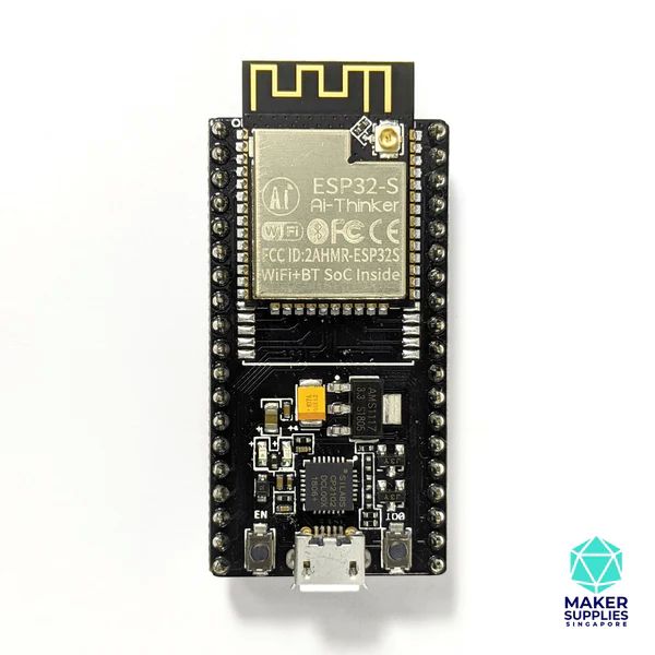
2.1 硬件
- ESP32 NodeMcu
- 中景园 1.3寸 240 x 240 TFT屏幕
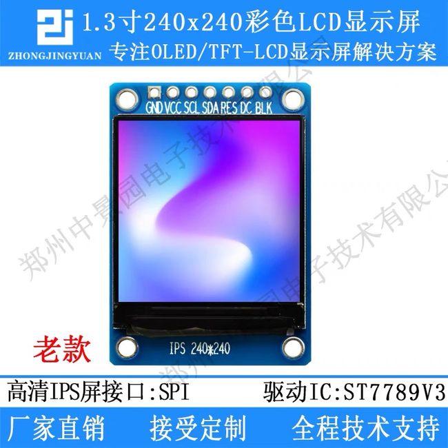
硬件引脚连接图
| ESP32 | TFT |
|---|---|
| GND | GND |
| 3V3 | VCC |
| 18 | SCL |
| 23 | SDA |
| 17 | RES |
| 16 | DC |
| 4 | BLK |
2.2 软件
- Python环境
配置好Python3环境,待会用来生成arduino 测试代码,直接运行
- Arduino ESP32环境
安装好这两个库。

- TFT_eSPI库
TFT_eSPI是一个功能强大的TFT屏幕驱动库
在Libraries里面搜索安装TFT_eSPI库到你的工程文件里面
然后修改 User_Setup.h文件
//                            USER DEFINED SETTINGS
//   Set driver type, fonts to be loaded, pins used and SPI control method etc
//
//   See the User_Setup_Select.h file if you wish to be able to define multiple
//   setups and then easily select which setup file is used by the compiler.
//
//   If this file is edited correctly then all the library example sketches should
//   run without the need to make any more changes for a particular hardware setup!
//   Note that some sketches are designed for a particular TFT pixel width/height

// User defined information reported by "Read_User_Setup" test & diagnostics example
#define USER_SETUP_INFO "User_Setup"

// Define to disable all #warnings in library (can be put in User_Setup_Select.h)
//#define DISABLE_ALL_LIBRARY_WARNINGS

// ##################################################################################
//
// Section 1. Call up the right driver file and any options for it
//
// ##################################################################################

// Define STM32 to invoke optimised processor support (only for STM32)
//#define STM32

// Defining the STM32 board allows the library to optimise the performance
// for UNO compatible "MCUfriend" style shields
//#define NUCLEO_64_TFT
//#define NUCLEO_144_TFT

// STM32 8 bit parallel only:
// If STN32 Port A or B pins 0-7 are used for 8 bit parallel data bus bits 0-7
// then this will improve rendering performance by a factor of ~8x
//#define STM_PORTA_DATA_BUS
//#define STM_PORTB_DATA_BUS

// Tell the library to use parallel mode (otherwise SPI is assumed)
//#define TFT_PARALLEL_8_BIT
//#defined TFT_PARALLEL_16_BIT // **** 16 bit parallel ONLY for RP2040 processor ****

// Display type -  only define if RPi display
//#define RPI_DISPLAY_TYPE // 20MHz maximum SPI

// Only define one driver, the other ones must be commented out
// #define ILI9341_DRIVER       // Generic driver for common displays
//#define ILI9341_2_DRIVER     // Alternative ILI9341 driver, see https://github.com/Bodmer/TFT_eSPI/issues/1172
//#define ST7735_DRIVER      // Define additional parameters below for this display
//#define ILI9163_DRIVER     // Define additional parameters below for this display
//#define S6D02A1_DRIVER
//#define RPI_ILI9486_DRIVER // 20MHz maximum SPI
//#define HX8357D_DRIVER
//#define ILI9481_DRIVER
//#define ILI9486_DRIVER
//#define ILI9488_DRIVER     // WARNING: Do not connect ILI9488 display SDO to MISO if other devices share the SPI bus (TFT SDO does NOT tristate when CS is high)
#define ST7789_DRIVER      // Full configuration option, define additional parameters below for this display
//#define ST7789_2_DRIVER    // Minimal configuration option, define additional parameters below for this display
//#define R61581_DRIVER
//#define RM68140_DRIVER
//#define ST7796_DRIVER
//#define SSD1351_DRIVER
//#define SSD1963_480_DRIVER
//#define SSD1963_800_DRIVER
//#define SSD1963_800ALT_DRIVER
//#define ILI9225_DRIVER
//#define GC9A01_DRIVER

// Some displays support SPI reads via the MISO pin, other displays have a single
// bi-directional SDA pin and the library will try to read this via the MOSI line.
// To use the SDA line for reading data from the TFT uncomment the following line:

// #define TFT_SDA_READ      // This option is for ESP32 ONLY, tested with ST7789 and GC9A01 display only

// For ST7735, ST7789 and ILI9341 ONLY, define the colour order IF the blue and red are swapped on your display
// Try ONE option at a time to find the correct colour order for your display

//  #define TFT_RGB_ORDER TFT_RGB  // Colour order Red-Green-Blue
//  #define TFT_RGB_ORDER TFT_BGR  // Colour order Blue-Green-Red

// For M5Stack ESP32 module with integrated ILI9341 display ONLY, remove // in line below

// #define M5STACK

// For ST7789, ST7735, ILI9163 and GC9A01 ONLY, define the pixel width and height in portrait orientation
// #define TFT_WIDTH  80
// #define TFT_WIDTH  128
// #define TFT_WIDTH  172 // ST7789 172 x 320
// #define TFT_WIDTH  170 // ST7789 170 x 320
#define TFT_WIDTH  240 // ST7789 240 x 240 and 240 x 320
// #define TFT_HEIGHT 160
// #define TFT_HEIGHT 128
#define TFT_HEIGHT 240 // ST7789 240 x 240
// #define TFT_HEIGHT 320 // ST7789 240 x 320
// #define TFT_HEIGHT 240 // GC9A01 240 x 240

// For ST7735 ONLY, define the type of display, originally this was based on the
// colour of the tab on the screen protector film but this is not always true, so try
// out the different options below if the screen does not display graphics correctly,
// e.g. colours wrong, mirror images, or stray pixels at the edges.
// Comment out ALL BUT ONE of these options for a ST7735 display driver, save this
// this User_Setup file, then rebuild and upload the sketch to the board again:

// #define ST7735_INITB
// #define ST7735_GREENTAB
// #define ST7735_GREENTAB2
// #define ST7735_GREENTAB3
// #define ST7735_GREENTAB128    // For 128 x 128 display
// #define ST7735_GREENTAB160x80 // For 160 x 80 display (BGR, inverted, 26 offset)
// #define ST7735_ROBOTLCD       // For some RobotLCD arduino shields (128x160, BGR, https://docs.arduino.cc/retired/getting-started-guides/TFT)
// #define ST7735_REDTAB
// #define ST7735_BLACKTAB
// #define ST7735_REDTAB160x80   // For 160 x 80 display with 24 pixel offset

// If colours are inverted (white shows as black) then uncomment one of the next
// 2 lines try both options, one of the options should correct the inversion.

// #define TFT_INVERSION_ON
// #define TFT_INVERSION_OFF


// ##################################################################################
//
// Section 2. Define the pins that are used to interface with the display here
//
// ##################################################################################

// If a backlight control signal is available then define the TFT_BL pin in Section 2
// below. The backlight will be turned ON when tft.begin() is called, but the library
// needs to know if the LEDs are ON with the pin HIGH or LOW. If the LEDs are to be
// driven with a PWM signal or turned OFF/ON then this must be handled by the user
// sketch. e.g. with digitalWrite(TFT_BL, LOW);

// #define TFT_BL   32            // LED back-light control pin
// #define TFT_BACKLIGHT_ON HIGH  // Level to turn ON back-light (HIGH or LOW)


// We must use hardware SPI, a minimum of 3 GPIO pins is needed.
// Typical setup for ESP8266 NodeMCU ESP-12 is :
//
// Display SDO/MISO  to NodeMCU pin D6 (or leave disconnected if not reading TFT)
// Display LED       to NodeMCU pin VIN (or 5V, see below)
// Display SCK       to NodeMCU pin D5
// Display SDI/MOSI  to NodeMCU pin D7
// Display DC (RS/AO)to NodeMCU pin D3
// Display RESET     to NodeMCU pin D4 (or RST, see below)
// Display CS        to NodeMCU pin D8 (or GND, see below)
// Display GND       to NodeMCU pin GND (0V)
// Display VCC       to NodeMCU 5V or 3.3V
//
// The TFT RESET pin can be connected to the NodeMCU RST pin or 3.3V to free up a control pin
//
// The DC (Data Command) pin may be labelled AO or RS (Register Select)
//
// With some displays such as the ILI9341 the TFT CS pin can be connected to GND if no more
// SPI devices (e.g. an SD Card) are connected, in this case comment out the #define TFT_CS
// line below so it is NOT defined. Other displays such at the ST7735 require the TFT CS pin
// to be toggled during setup, so in these cases the TFT_CS line must be defined and connected.
//
// The NodeMCU D0 pin can be used for RST
//
//
// Note: only some versions of the NodeMCU provide the USB 5V on the VIN pin
// If 5V is not available at a pin you can use 3.3V but backlight brightness
// will be lower.


// ###### EDIT THE PIN NUMBERS IN THE LINES FOLLOWING TO SUIT YOUR ESP8266 SETUP ######

// For NodeMCU - use pin numbers in the form PIN_Dx where Dx is the NodeMCU pin designation
// #define TFT_MISO  PIN_D6  // Automatically assigned with ESP8266 if not defined
// #define TFT_MOSI  PIN_D7  // Automatically assigned with ESP8266 if not defined
// #define TFT_SCLK  PIN_D5  // Automatically assigned with ESP8266 if not defined

// #define TFT_CS    PIN_D8  // Chip select control pin D8
// #define TFT_DC    PIN_D3  // Data Command control pin
// #define TFT_RST   PIN_D4  // Reset pin (could connect to NodeMCU RST, see next line)
//#define TFT_RST  -1     // Set TFT_RST to -1 if the display RESET is connected to NodeMCU RST or 3.3V


//#define TFT_BL PIN_D1  // LED back-light (only for ST7789 with backlight control pin)

//#define TOUCH_CS PIN_D2     // Chip select pin (T_CS) of touch screen

//#define TFT_WR PIN_D2       // Write strobe for modified Raspberry Pi TFT only


// ######  FOR ESP8266 OVERLAP MODE EDIT THE PIN NUMBERS IN THE FOLLOWING LINES  ######

// Overlap mode shares the ESP8266 FLASH SPI bus with the TFT so has a performance impact
// but saves pins for other functions. It is best not to connect MISO as some displays
// do not tristate that line when chip select is high!
// Note: Only one SPI device can share the FLASH SPI lines, so a SPI touch controller
// cannot be connected as well to the same SPI signals.
// On NodeMCU 1.0 SD0=MISO, SD1=MOSI, CLK=SCLK to connect to TFT in overlap mode
// On NodeMCU V3  S0 =MISO, S1 =MOSI, S2 =SCLK
// In ESP8266 overlap mode the following must be defined

//#define TFT_SPI_OVERLAP

// In ESP8266 overlap mode the TFT chip select MUST connect to pin D3
//#define TFT_CS   PIN_D3
//#define TFT_DC   PIN_D5  // Data Command control pin
//#define TFT_RST  PIN_D4  // Reset pin (could connect to NodeMCU RST, see next line)
//#define TFT_RST  -1  // Set TFT_RST to -1 if the display RESET is connected to NodeMCU RST or 3.3V


// ###### EDIT THE PIN NUMBERS IN THE LINES FOLLOWING TO SUIT YOUR ESP32 SETUP   ######

// For ESP32 Dev board (only tested with ILI9341 display)
// The hardware SPI can be mapped to any pins

// #define TFT_MISO 19
// #define TFT_MOSI 23
// #define TFT_SCLK 18
// #define TFT_CS   5  // Chip select control pin
// #define TFT_DC    27  // Data Command control pin
// #define TFT_RST   26  // Reset pin (could connect to RST pin)
// #define TFT_RST  -1  // Set TFT_RST to -1 if display RESET is connected to ESP32 board RST

// For ESP32 Dev board (only tested with GC9A01 display)
// The hardware SPI can be mapped to any pins

#define TFT_MOSI 23 // In some display driver board, it might be written as "SDA" and so on.
#define TFT_SCLK 18
#define TFT_CS   5  // Chip select control pin
#define TFT_DC   16  // Data Command control pin
#define TFT_RST  17  // Reset pin (could connect to Arduino RESET pin)
#define TFT_BL   4  // LED back-light

//#define TOUCH_CS 21     // Chip select pin (T_CS) of touch screen

//#define TFT_WR 22    // Write strobe for modified Raspberry Pi TFT only

// For the M5Stack module use these #define lines
//#define TFT_MISO 19
//#define TFT_MOSI 23
//#define TFT_SCLK 18
//#define TFT_CS   14  // Chip select control pin
//#define TFT_DC   27  // Data Command control pin
//#define TFT_RST  33  // Reset pin (could connect to Arduino RESET pin)
//#define TFT_BL   32  // LED back-light (required for M5Stack)

// ######       EDIT THE PINs BELOW TO SUIT YOUR ESP32 PARALLEL TFT SETUP        ######

// The library supports 8 bit parallel TFTs with the ESP32, the pin
// selection below is compatible with ESP32 boards in UNO format.
// Wemos D32 boards need to be modified, see diagram in Tools folder.
// Only ILI9481 and ILI9341 based displays have been tested!

// Parallel bus is only supported for the STM32 and ESP32
// Example below is for ESP32 Parallel interface with UNO displays

// Tell the library to use 8 bit parallel mode (otherwise SPI is assumed)
//#define TFT_PARALLEL_8_BIT

// The ESP32 and TFT the pins used for testing are:
//#define TFT_CS   33  // Chip select control pin (library pulls permanently low
//#define TFT_DC   15  // Data Command control pin - must use a pin in the range 0-31
//#define TFT_RST  32  // Reset pin, toggles on startup

//#define TFT_WR    4  // Write strobe control pin - must use a pin in the range 0-31
//#define TFT_RD    2  // Read strobe control pin

//#define TFT_D0   12  // Must use pins in the range 0-31 for the data bus
//#define TFT_D1   13  // so a single register write sets/clears all bits.
//#define TFT_D2   26  // Pins can be randomly assigned, this does not affect
//#define TFT_D3   25  // TFT screen update performance.
//#define TFT_D4   17
//#define TFT_D5   16
//#define TFT_D6   27
//#define TFT_D7   14

// ######       EDIT THE PINs BELOW TO SUIT YOUR STM32 SPI TFT SETUP        ######

// The TFT can be connected to SPI port 1 or 2
//#define TFT_SPI_PORT 1 // SPI port 1 maximum clock rate is 55MHz
//#define TFT_MOSI PA7
//#define TFT_MISO PA6
//#define TFT_SCLK PA5

//#define TFT_SPI_PORT 2 // SPI port 2 maximum clock rate is 27MHz
//#define TFT_MOSI PB15
//#define TFT_MISO PB14
//#define TFT_SCLK PB13

// Can use Ardiuno pin references, arbitrary allocation, TFT_eSPI controls chip select
//#define TFT_CS   D5 // Chip select control pin to TFT CS
//#define TFT_DC   D6 // Data Command control pin to TFT DC (may be labelled RS = Register Select)
//#define TFT_RST  D7 // Reset pin to TFT RST (or RESET)
// OR alternatively, we can use STM32 port reference names PXnn
//#define TFT_CS   PE11 // Nucleo-F767ZI equivalent of D5
//#define TFT_DC   PE9  // Nucleo-F767ZI equivalent of D6
//#define TFT_RST  PF13 // Nucleo-F767ZI equivalent of D7

//#define TFT_RST  -1   // Set TFT_RST to -1 if the display RESET is connected to processor reset
                        // Use an Arduino pin for initial testing as connecting to processor reset
                        // may not work (pulse too short at power up?)

// ##################################################################################
//
// Section 3. Define the fonts that are to be used here
//
// ##################################################################################

// Comment out the #defines below with // to stop that font being loaded
// The ESP8366 and ESP32 have plenty of memory so commenting out fonts is not
// normally necessary. If all fonts are loaded the extra FLASH space required is
// about 17Kbytes. To save FLASH space only enable the fonts you need!

#define LOAD_GLCD   // Font 1. Original Adafruit 8 pixel font needs ~1820 bytes in FLASH
#define LOAD_FONT2  // Font 2. Small 16 pixel high font, needs ~3534 bytes in FLASH, 96 characters
#define LOAD_FONT4  // Font 4. Medium 26 pixel high font, needs ~5848 bytes in FLASH, 96 characters
#define LOAD_FONT6  // Font 6. Large 48 pixel font, needs ~2666 bytes in FLASH, only characters 1234567890:-.apm
#define LOAD_FONT7  // Font 7. 7 segment 48 pixel font, needs ~2438 bytes in FLASH, only characters 1234567890:-.
#define LOAD_FONT8  // Font 8. Large 75 pixel font needs ~3256 bytes in FLASH, only characters 1234567890:-.
//#define LOAD_FONT8N // Font 8. Alternative to Font 8 above, slightly narrower, so 3 digits fit a 160 pixel TFT
#define LOAD_GFXFF  // FreeFonts. Include access to the 48 Adafruit_GFX free fonts FF1 to FF48 and custom fonts

// Comment out the #define below to stop the SPIFFS filing system and smooth font code being loaded
// this will save ~20kbytes of FLASH
#define SMOOTH_FONT


// ##################################################################################
//
// Section 4. Other options
//
// ##################################################################################

// For RP2040 processor and SPI displays, uncomment the following line to use the PIO interface.
//#define RP2040_PIO_SPI // Leave commented out to use standard RP2040 SPI port interface

// For RP2040 processor and 8 or 16 bit parallel displays:
// The parallel interface write cycle period is derived from a division of the CPU clock
// speed so scales with the processor clock. This means that the divider ratio may need
// to be increased when overclocking. It may also need to be adjusted dependant on the
// display controller type (ILI94341, HX8357C etc). If RP2040_PIO_CLK_DIV is not defined
// the library will set default values which may not suit your display.
// The display controller data sheet will specify the minimum write cycle period. The
// controllers often work reliably for shorter periods, however if the period is too short
// the display may not initialise or graphics will become corrupted.
// PIO write cycle frequency = (CPU clock/(4 * RP2040_PIO_CLK_DIV))
//#define RP2040_PIO_CLK_DIV 1 // 32ns write cycle at 125MHz CPU clock
//#define RP2040_PIO_CLK_DIV 2 // 64ns write cycle at 125MHz CPU clock
//#define RP2040_PIO_CLK_DIV 3 // 96ns write cycle at 125MHz CPU clock

// For the RP2040 processor define the SPI port channel used (default 0 if undefined)
//#define TFT_SPI_PORT 1 // Set to 0 if SPI0 pins are used, or 1 if spi1 pins used

// For the STM32 processor define the SPI port channel used (default 1 if undefined)
//#define TFT_SPI_PORT 2 // Set to 1 for SPI port 1, or 2 for SPI port 2

// Define the SPI clock frequency, this affects the graphics rendering speed. Too
// fast and the TFT driver will not keep up and display corruption appears.
// With an ILI9341 display 40MHz works OK, 80MHz sometimes fails
// With a ST7735 display more than 27MHz may not work (spurious pixels and lines)
// With an ILI9163 display 27 MHz works OK.

// #define SPI_FREQUENCY   1000000
// #define SPI_FREQUENCY   5000000
// #define SPI_FREQUENCY  10000000
// #define SPI_FREQUENCY  20000000
#define SPI_FREQUENCY  27000000
// #define SPI_FREQUENCY  40000000
// #define SPI_FREQUENCY  55000000 // STM32 SPI1 only (SPI2 maximum is 27MHz)
// #define SPI_FREQUENCY  80000000

// Optional reduced SPI frequency for reading TFT
#define SPI_READ_FREQUENCY  20000000

// The XPT2046 requires a lower SPI clock rate of 2.5MHz so we define that here:
#define SPI_TOUCH_FREQUENCY  2500000

// The ESP32 has 2 free SPI ports i.e. VSPI and HSPI, the VSPI is the default.
// If the VSPI port is in use and pins are not accessible (e.g. TTGO T-Beam)
// then uncomment the following line:
//#define USE_HSPI_PORT

// Comment out the following #define if "SPI Transactions" do not need to be
// supported. When commented out the code size will be smaller and sketches will
// run slightly faster, so leave it commented out unless you need it!

// Transaction support is needed to work with SD library but not needed with TFT_SdFat
// Transaction support is required if other SPI devices are connected.

// Transactions are automatically enabled by the library for an ESP32 (to use HAL mutex)
// so changing it here has no effect

// #define SUPPORT_TRANSACTIONS
- TJpg_Decoder库
用于JEPG的解码
https://github.com/Bodmer/TJpg_Decoder
在Libraries里面搜索安装TJpg_Decoder库到你的工程文件里面
3. 图片效果
3.1 显示BMP图片
这里使用测试代码 bmp.

对应源码:
#include 替换图片操作步骤。
需要利用工具 lcd-image-converter 把BMP图片转成HEX数组。
比如这里,我测试了
工具操作步骤:
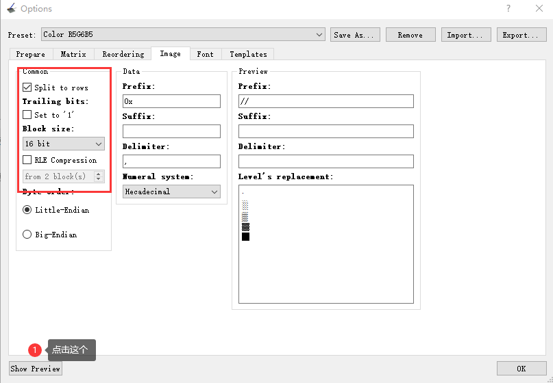
- 用 lcd-image-converter 工具打开BMP图片
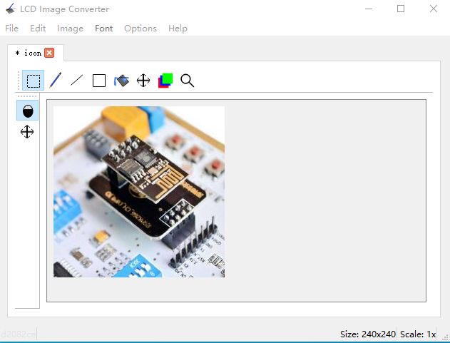
- 选择Options->Conversion->选择 Color R5G6B5,然后设置Image,点击Preview
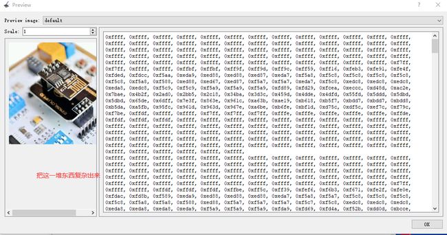
把以上数组直接复制出来,然后覆盖掉bmp.h文件里面的数组定义,就能
得到具体效果了。
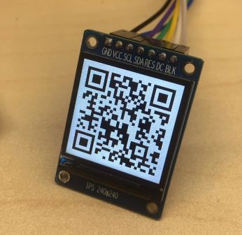
3.2 显示二维码PNG图片,支持Python脚本生成代码
为了快速显示一个PNG图片。这里弄了一个生成代码的python脚本。

直接看 png2hex.py 脚本代码。
from PIL import Image,ImageOps
import os, traceback
from io import BytesIO
import binascii
'''
参考链接
https://stackoverflow.com/questions/10269099/pil-convert-gif-frames-to-jpg
'''
curdir = "./"
os.chdir(curdir)
inoInfo = """#include <TFT_eSPI.h>
#include \n\n' )
print('.', end="")
new_im = Image.new("RGB", im.size)
new_im.paste(im)
# 缩放图像,
width = new_im.size[0] # 获取原始图像宽度
height = new_im.size[1] # 获取原始图像高度
# 等比例缩放后的图像高度,根据实际需要调整
print(width, " ", height)
if height > size[1] or width > size[0]:
new_im = ImageOps.fit(new_im,size,Image.LANCZOS)
print("after", new_im.size[0], " ", new_im.size[1])
# 获取图像字节流,转16进制格式
img_byte = BytesIO() # 获取字节流
new_im.save(img_byte, format='jpeg')
# 16进制字符串
img_hex = binascii.hexlify(img_byte.getvalue()).decode('utf-8')
arr_name = filename + '_' + str(i)
arr_size = 0 # 记录数组长度
arr_name_all += arr_name + ','
# 将ac --> 0xac
f.write('const uint8_t ' + arr_name + '[] PROGMEM = { \n') # 写前
for index, x in zip(range(len(img_hex)), range(0, len(img_hex), 2)):
temp_hex = '0x' + img_hex[x:x + 2] + ', '
# 30个数据换行
if (index + 1) % 30 == 0:
temp_hex += '\n'
f.write(temp_hex) # 写入文件
arr_size += 1
f.write('\n};\n\n') # 写结尾
i += 1
arr_size_all += str(arr_size) + ','
# 保存一帧帧图像
if saveImg:
if not os.path.exists('./out_img'):
os.mkdir('./out_img')
if not os.path.exists('./out_img/' + filename):
os.mkdir('./out_img/' + filename)
new_im.save('./out_img/' + filename + '/' + str(i) + '.jpg')
# 动图读取结束
f.write('const uint8_t *' + filename + '[' + str(i) + '] PROGMEM = { ' + arr_name_all + '};\n')
f.write('const uint32_t ' + filename + '_size[' + str(i) + '] PROGMEM = { ' + arr_size_all + '};')
print("成功保存文件为:" + filename + '.h')
# 再生成一个 ino arduino文件
with open(cacheFileName + '.ino', 'w', encoding='utf-8') as f2: # 写入文件
# 写个头文件
f2.write(inoInfo.replace('[gif]',filename))
except EOFError as e:
print(e.args)
print(traceback.format_exc())
pass # end of sequence
if __name__ == '__main__':
processImage('icon_me.png',(70, 70))
processImage('qrcode.png',(240, 240))
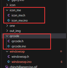
在Python3环境下执行脚本
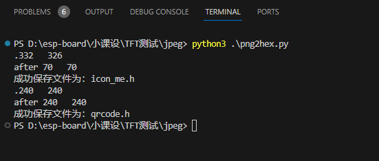
就会生成两个Arduino工程文件。
直接编译烧录到目标板子即可。
3.3 显示JPEG图片,支持Python脚本生成代码
同样的道理,这里也有一个脚本用于生成JPEG图片显示。

这里也顺便看看 jpeg2hex.py 脚本源码。
from PIL import Image,ImageOps
import os, traceback
from io import BytesIO
import binascii
'''
参考链接
https://stackoverflow.com/questions/10269099/pil-convert-gif-frames-to-jpg
'''
curdir = "./"
os.chdir(curdir)
inoInfo = """#include <TFT_eSPI.h>
#include \n\n' )
print('.', end="")
new_im = Image.new("RGB", im.size)
new_im.paste(im)
# 缩放图像,
width = new_im.size[0] # 获取原始图像宽度
height = new_im.size[1] # 获取原始图像高度
# 等比例缩放后的图像高度,根据实际需要调整
print(width, " ", height)
if height > size[1] or width > size[0]:
new_im = ImageOps.fit(new_im,size,Image.LANCZOS)
print("after", new_im.size[0], " ", new_im.size[1])
# 获取图像字节流,转16进制格式
img_byte = BytesIO() # 获取字节流
new_im.save(img_byte, format='jpeg')
# 16进制字符串
img_hex = binascii.hexlify(img_byte.getvalue()).decode('utf-8')
arr_name = filename + '_' + str(i)
arr_size = 0 # 记录数组长度
arr_name_all += arr_name + ','
# 将ac --> 0xac
f.write('const uint8_t ' + arr_name + '[] PROGMEM = { \n') # 写前
for index, x in zip(range(len(img_hex)), range(0, len(img_hex), 2)):
temp_hex = '0x' + img_hex[x:x + 2] + ', '
# 30个数据换行
if (index + 1) % 30 == 0:
temp_hex += '\n'
f.write(temp_hex) # 写入文件
arr_size += 1
f.write('\n};\n\n') # 写结尾
i += 1
arr_size_all += str(arr_size) + ','
# 保存一帧帧图像
if saveImg:
if not os.path.exists('./out_img'):
os.mkdir('./out_img')
if not os.path.exists('./out_img/' + filename):
os.mkdir('./out_img/' + filename)
new_im.save('./out_img/' + filename + '/' + str(i) + '.jpg')
# 保存一帧帧图像
if saveImg:
if not os.path.exists('./out_img'):
os.mkdir('./out_img')
if not os.path.exists('./out_img/' + filename):
os.mkdir('./out_img/' + filename)
new_im.save('./out_img/' + filename + '/' + str(i) + '.jpg')
# 动图读取结束
f.write('const uint8_t *' + filename + '[' + str(i) + '] PROGMEM = { ' + arr_name_all + '};\n')
f.write('const uint32_t ' + filename + '_size[' + str(i) + '] PROGMEM = { ' + arr_size_all + '};')
print("成功保存文件为:" + filename + '.h')
# 再生成一个 ino arduino文件
with open(cacheFileName + '.ino', 'w', encoding='utf-8') as f2: # 写入文件
# 写个头文件
f2.write(inoInfo.replace('[gif]',filename))
except EOFError as e:
print(e.args)
print(traceback.format_exc())
pass # end of sequence
if __name__ == '__main__':
processImage('icon.jpg',(150, 150))
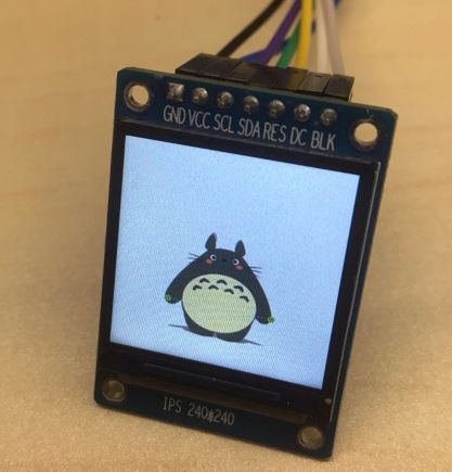
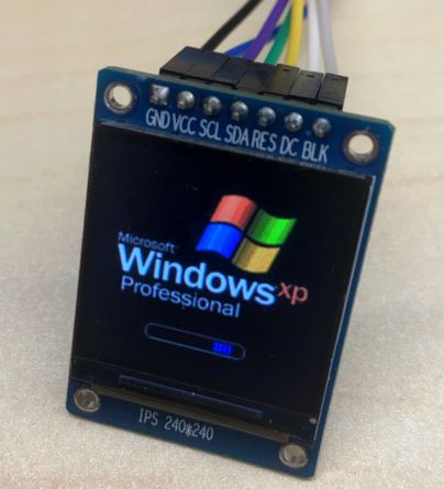
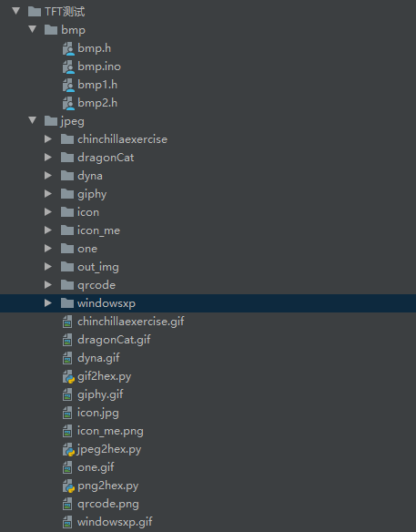
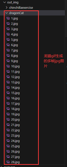
3.4 显示Gif图片,支持Python脚本生成代码
这里博主测试了多个gif,一键生成代码。
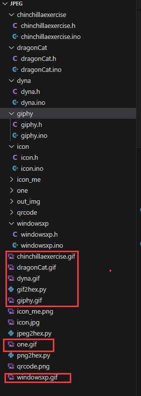
同样的道理,这里也有一个脚本用于生成GIF图片显示。
gif文件,本质就是多帧图片。
同样的,我们也要学习一下脚本。
from PIL import Image,ImageOps
import os, traceback
from io import BytesIO
import binascii
'''
参考链接
https://stackoverflow.com/questions/10269099/pil-convert-gif-frames-to-jpg
'''
curdir = "./"
os.chdir(curdir)
inoInfo = """#include <TFT_eSPI.h>
#include \n\n' )
while 1:
print('.', end="")
new_im = Image.new("RGB", im.size)
new_im.paste(im)
# 缩放图像,
width = new_im.size[0] # 获取原始图像宽度
height = new_im.size[1] # 获取原始图像高度
# 等比例缩放后的图像高度,根据实际需要调整
print(width, " ", height)
if height > size[1] or width > size[0]:
new_im = ImageOps.fit(new_im,size,Image.LANCZOS)
print("after", new_im.size[0], " ", new_im.size[1])
# 获取图像字节流,转16进制格式
img_byte = BytesIO() # 获取字节流
new_im.save(img_byte, format='jpeg')
# 16进制字符串
img_hex = binascii.hexlify(img_byte.getvalue()).decode('utf-8')
arr_name = filename + '_' + str(i)
arr_size = 0 # 记录数组长度
arr_name_all += arr_name + ','
# 将ac --> 0xac
f.write('const uint8_t ' + arr_name + '[] PROGMEM = { \n') # 写前
for index, x in zip(range(len(img_hex)), range(0, len(img_hex), 2)):
temp_hex = '0x' + img_hex[x:x + 2] + ', '
# 30个数据换行
if (index + 1) % 30 == 0:
temp_hex += '\n'
f.write(temp_hex) # 写入文件
arr_size += 1
f.write('\n};\n\n') # 写结尾
i += 1
arr_size_all += str(arr_size) + ','
# 保存一帧帧图像
if saveImg:
if not os.path.exists('./out_img'):
os.mkdir('./out_img')
if not os.path.exists('./out_img/' + filename):
os.mkdir('./out_img/' + filename)
new_im.save('./out_img/' + filename + '/' + str(i) + '.jpg')
try:
im.seek(im.tell() + 1)
except EOFError:
# 动图读取结束
f.write('const uint8_t *' + filename + '[' + str(i) + '] PROGMEM = { ' + arr_name_all + '};\n')
f.write('const uint32_t ' + filename + '_size[' + str(i) + '] PROGMEM = { ' + arr_size_all + '};')
print("成功保存文件为:" + filename + '.h')
# 再生成一个 ino arduino文件
with open(cacheFileName + '.ino', 'w', encoding='utf-8') as f2: # 写入文件
# 写个头文件
f2.write(inoInfo.replace('[gif]',filename))
break
except EOFError as e:
print(e.args)
print(traceback.format_exc())
pass # end of sequence
if __name__ == '__main__':
processImage('chinchillaexercise.gif',(240, 240))
processImage('one.gif',(240, 240))
processImage('giphy.gif',(240, 240))
processImage('windowsxp.gif',(240, 240))
processImage('dragonCat.gif',(240, 240))
processImage('dyna.gif',(240, 240))