全志V3S嵌入式驱动开发(lcd屏幕驱动)
【 声明:版权所有,欢迎转载,请勿用于商业用途。 联系信箱:feixiaoxing @163.com】
对于一些设备,人们是希望从屏幕上面获取结果信息的,这样也显得更直观一些。另外,也有一些设备,它本身是需要客户和它不停交互,去一起完成某个功能的,这个时候,我们就要引入电容屏或者电阻屏了。那么,对于v3s来说,如果需要完成lcd屏幕的驱动和显示,需要完成哪些工作呢,这部分今天大家可以一起讨论下。
1、重新编译uboot
重新编译uboot代码,这部分是最容易被忽视的。驱动之前的几种设备时,大家选用的配置文件一般是LicheePi_Zero_defconfig。但是,如今我们需要驱动lcd屏幕,以480*272的分辨率为例,就要使用LicheePi_Zero_480x272LCD_defconfig这个文件。
make ARCH=arm LicheePi_Zero_480x272LCD_defconfig
make ARCH=arm CROSS_COMPILE=arm-linux-gnueabihf-
编译完成之后,直接在ubuntu虚拟机里面把u-boot-sunxi-with-spl.bin烧入到sd卡即可,
sudo dd if=u-boot-sunxi-with-spl.bin of=/dev/sdb bs=1024 seek=82、配置dts文件
这里说的dts文件是指linux的dts文件,不是uboot的dts文件。kernel本身还是4.14.y这个版本。在配置之前,前期因为测试各个驱动所作的修改,最好恢复到和以前一样,然后接下来有两个地方需要重新配置下,一个是sun8i-v3s-licheepi-zero-with-lcd.dtsi这个文件,
/*
 * Copyright (C) 2018 Icenowy Zheng
 *
 * SPDX-License-Identifier: (GPL-2.0+ OR X11)
 */

#include "sun8i-v3s-licheepi-zero.dts"

/ {
/*	backlight: backlight {
		compatible = "pwm-backlight";
		pwms = <&pwm 0 1000000 0>;
		brightness-levels = <0 30 40 50 60 70 100>;
		default-brightness-level = <6>;
	};*/

	panel: panel {
		#address-cells = <1>;
		#size-cells = <0>;

		port@0 {
			reg = <0>;
		/*	backlight = <&backlight>;*/
			#address-cells = <1>;
			#size-cells = <0>;

			panel_input: endpoint@0 {
				reg = <0>;
				remote-endpoint = <&tcon0_out_lcd>;
			};
		};
	};
};

&de {
	status = "okay";
};

/*&pwm {
	pinctrl-names = "default";
	pinctrl-0 = <&pwm0_pins>;
	status = "okay";
};*/

&tcon0 {
	pinctrl-names = "default";
	pinctrl-0 = <&lcd_rgb666_pins_a>;
	status = "okay";
};

&tcon0_out {
	tcon0_out_lcd: endpoint@0 {
		reg = <0>;
		remote-endpoint = <&panel_input>;
	};
};

/delete-node/ &simplefb_lcd;
另外一个就是sun8i-v3s.dtsi文件,这里修改成60M,主要是为了6分频成10M,保持和uboot中的lcd频率一致,
assigned-clock-rates = <60000000>;经过了这两处修改之后,重新编译生成dtb文件,
make ARCH=arm CROSS_COMPILE=arm-linux-gnueabihf-编译完成之后,需要注意的是,这次sd卡里面烧入的应该是sun8i-v3s-licheepi-zero-with-480x272-lcd.dtb文件,而不应该是之前的sun8i-v3s-licheepi-zero-dock.dtb。
3、点亮屏幕
修改了uboot代码,重新烧录了dtb文件,但其实这个时候lcd屏幕依然还没有办法点亮,我们可以看一下电路图,

这幅图是lcd的原理图。整个信号分成三个部分,第一部分VLED-、VLED+,这个主要是点亮屏幕的背光灯使用的。第二部分D2-D23、CLK、HSYNC、VSYNC、DE,这些都是真正的数据传输信号,其中D2-D23一般就是R、G、B信号。第三部分TP信号,这四个主要是处理触摸屏的,后续遇到了再分析。
前面我们说过目前为止LCD还没有点亮,说的其实就是VLED-、VLED+还没有信号驱动,它的信号来自于芯片PT4103,
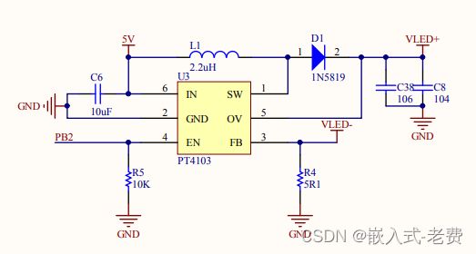
这个芯片的开关就在EN这个地方,而EN又是友PB2来控制的。之前的文章我们也说过,这个PA、PB...都可以看成是gpio端口,只需要设置对应的通道、方向和数值就可以了,像这样,
echo 34 > /sys/class/gpio/export
echo out > /sys/class/gpio/gpio34/direction
echo 1 > /sys/class/gpio/gpio34/value
为什么是34,我们讲过,从PA开始,channel = 32 * x + y,其中PB代表x=1,而PB2中的2,则代表y,所以通道是32 * 1 + 2= 34。经过上面的direction和value配置后,屏幕就会被点亮,虽然可能什么内容也没有显示。
4、验证驱动是否加载
验证lcd驱动是否可以正常运行,可以先查看是否有/dev/fb0这样一个设备节点,如果有,且linux kernel启动正常,一般就代表驱动ok了,没有问题了。如果还不放心,可以输入这个命令,
cat /dev/urandom > /dev/fb0执行过程中,如果遇到这样的输出错误打印,可以忽略,因为这是完全正常的,
# cat /dev/urandom > /dev/fb0
cat: write error: No space left on device
我们再看一眼屏幕,这个时候大概率就可以看到这样的效果了,主要就是一些噪声点显示,

5、自己编写程序验证
除了用随机点验证之外,我们还可以自己编写程序,直接控制/dev/fb0。下面这些程序都是从网上借鉴而来,主要为了学习使用,再次一并表示感谢。代码中为了适应480*272的lcd屏幕,部分代码做了修改。
5.1 读取屏幕驱动参数
#include
#include
#include
#include
#include
#include
#include

int main () {

 int fp=0;
 struct fb_var_screeninfo vinfo;
 struct fb_fix_screeninfo finfo;
 fp = open ("/dev/fb0",O_RDWR);


 if (fp < 0){
  printf("Error : Can not open framebuffer device/n");
  exit(1);
 }


 if (ioctl(fp,FBIOGET_FSCREENINFO,&finfo)){
  printf("Error reading fixed information/n");
  exit(2);
 }

 if (ioctl(fp,FBIOGET_VSCREENINFO,&vinfo)){
  printf("Error reading variable information/n");
  exit(3);
 }


 printf("The mem is :%d\n",finfo.smem_len);
 printf("The line_length is :%d\n",finfo.line_length);
 printf("The xres is :%d\n",vinfo.xres);
 printf("The yres is :%d\n",vinfo.yres);
 printf("bits_per_pixel is :%d\n",vinfo.bits_per_pixel);
 close (fp);
}
这个程序比较简单,就是读取了缓存大小、每一行字节数、x宽度、y宽度和每一个像素字节序信息。
5.2 在/dev/fb0上面绘制一个点
#include
#include
#include
#include
#include
#include
#include

int main () {

 int fp=0;
 struct fb_var_screeninfo vinfo;
 struct fb_fix_screeninfo finfo;
 long screensize=0;
 char *fbp = 0;
 int x = 0, y = 0;
 long location = 0;
 fp = open ("/dev/fb0",O_RDWR);


 if (fp < 0){
  printf("Error : Can not open framebuffer device/n");
  exit(1);
 }


 if (ioctl(fp,FBIOGET_FSCREENINFO,&finfo)){
  printf("Error reading fixed information/n");
  exit(2);
 }

 if (ioctl(fp,FBIOGET_VSCREENINFO,&vinfo)){
  printf("Error reading variable information/n");
  exit(3);
 }


 screensize = vinfo.xres * vinfo.yres * vinfo.bits_per_pixel / 8;
 fbp =(char *) mmap (0, screensize, PROT_READ | PROT_WRITE, MAP_SHARED, fp,0);
 if ((int) fbp == -1){
     printf ("Error: failed to map framebuffer device to memory./n");
     exit (4);
 }

  x = 100;
  y = 100;
  location = x * (vinfo.bits_per_pixel / 8) + y  *  finfo.line_length;

  *(fbp + location) = 100;
  *(fbp + location + 1) = 15;
  *(fbp + location + 2) = 200;
  *(fbp + location + 3) = 0;
  munmap (fbp, screensize);
  close (fp);
  return 0;
}
将程序编译后,上传到sd卡运行后,就会看到这样的一个斑点,还是比较好找的,

5.3 显示图片
#include
#include
#include
#include
#include
#include
#include
#include
#include
#include

//14byte文件头
typedef struct
{
    char    cfType[2];//文件类型,"BM"(0x4D42)
    int     cfSize;//文件大小(字节)
    int cfReserved;//保留,值为0
    int     cfoffBits;//数据区相对于文件头的偏移量(字节)
}__attribute__((packed)) BITMAPFILEHEADER;
//__attribute__((packed))的作用是告诉编译器取消结构在编译过程中的优化对齐

//40byte信息头
typedef struct
{
    char ciSize[4];//BITMAPFILEHEADER所占的字节数
    int  ciWidth;//宽度
    int  ciHeight;//高度
    char ciPlanes[2];//目标设备的位平面数,值为1
    int  ciBitCount;//每个像素的位数
    char ciCompress[4];//压缩说明
    char ciSizeImage[4];//用字节表示的图像大小,该数据必须是4的倍数
    char ciXPelsPerMeter[4];//目标设备的水平像素数/米
    char ciYPelsPerMeter[4];//目标设备的垂直像素数/米
    char ciClrUsed[4]; //位图使用调色板的颜色数
    char ciClrImportant[4]; //指定重要的颜色数,当该域的值等于颜色数时(或者等于0时),表示所有颜色都一样重要
}__attribute__((packed)) BITMAPINFOHEADER;

typedef struct
{
    unsigned char blue;
    unsigned char green;
    unsigned char red;
    unsigned char reserved;
}__attribute__((packed)) PIXEL;//颜色模式RGB

BITMAPFILEHEADER FileHead;
BITMAPINFOHEADER InfoHead;

static char *fbp = 0;
static int xres = 0;
static int yres = 0;
static int bits_per_pixel = 0;
int width, height;

int show_bmp();
int fbfd = 0;

static void fb_update(struct fb_var_screeninfo *vi)   //将要渲染的图形缓冲区的内容绘制到设备显示屏来
{
    vi->yoffset = 1;
    ioctl(fbfd, FBIOPUT_VSCREENINFO, vi);
    vi->yoffset = 0;
    ioctl(fbfd, FBIOPUT_VSCREENINFO, vi);
}

static int cursor_bitmap_format_convert(char *dst,char *src)
{
    int i ,j ;
    char *psrc = src ;
    char *pdst = dst;
    char *p = psrc;

    /* 由于bmp存储是从后面往前面,所以需要倒序进行转换 */
    pdst += (width * height * 4);
    for(i=0;i malloc bmp out of memory!\n");
        return -1;
    }

    /* 再移位到文件头部 */
    fseek(fp,0,SEEK_SET);

    rc = fread(&FileHead, sizeof(BITMAPFILEHEADER),1, fp);
    if ( rc != 1)
    {
        printf("read header error!\n");
        fclose( fp );
        return( -2 );
    }

    //检测是否是bmp图像
    if (memcmp(FileHead.cfType, "BM", 2) != 0)
    {
        printf("it's not a BMP file\n");
        fclose( fp );
        return( -3 );
    }
    rc = fread( (char *)&InfoHead, sizeof(BITMAPINFOHEADER),1, fp );
    if ( rc != 1)
    {
        printf("read infoheader error!\n");
        fclose( fp );
        return( -4 );
    }
    width = InfoHead.ciWidth;
    height = InfoHead.ciHeight;

    printf("FileHead.cfSize =%d byte\n",FileHead.cfSize);
    printf("flen = %d\n", flen);
    printf("width = %d, height = %d\n", width, height);

    total_length = width * height *3;

    printf("total_length = %d\n", total_length);

    //跳转的数据区
    fseek(fp, FileHead.cfoffBits, SEEK_SET);
    printf(" FileHead.cfoffBits = %d\n",  FileHead.cfoffBits);
    printf(" InfoHead.ciBitCount = %d\n",  InfoHead.ciBitCount);

    //每行字节数
    buf = bmp_buf;
    while ((ret = fread(buf,1,total_length,fp)) >= 0) {
        if (ret == 0) {
            usleep(100);
            continue;
        }
        printf("ret = %d\n", ret);
        buf = ((char*) buf) + ret;
        total_length = total_length - ret;
        if(total_length == 0)
            break;
    }

    ///重新计算,很重要!!
    total_length = width * height *4;
    bmp_buf_dst = (char*)calloc(1,total_length );
    if(bmp_buf_dst == NULL){
        printf("load > malloc bmp out of memory!\n");
        return -1;
    }

    cursor_bitmap_format_convert(bmp_buf_dst, bmp_buf);
    memcpy(fbp,bmp_buf_dst,total_length);

    free(bmp_buf);
    free(bmp_buf_dst);

    fclose(fp);
    printf("show logo return 0\n");
    return 0;
}

int show_picture(int fd, char *path)
{
    struct fb_var_screeninfo vinfo;
    struct fb_fix_screeninfo finfo;
    long int screensize = 0;
    struct fb_bitfield red;
    struct fb_bitfield green;
    struct fb_bitfield blue;

    //打开显示设备
    fbfd = fd;          //open("/dev/graphics/fb0", O_RDWR);
    printf("fbfd = %d\n", fbfd);
    if (fbfd == -1)
    {
        //printf("Error opening frame buffer errno=%d (%s)\n",errno, strerror(errno));
        return -1;
    }

    if (ioctl(fbfd, FBIOGET_FSCREENINFO, &finfo))
    {
        //printf("Error:reading fixed information.\n");
        return -1;
    }

    if (ioctl(fbfd, FBIOGET_VSCREENINFO, &vinfo))
    {
        //printf("Error: reading variable information.\n");
        return -1;
    }

    //printf("R:%x ;G:%d ;B:%d \n", (int)vinfo.red, vinfo.green, vinfo.blue );
    //printf("%dx%d, %dbpp\n", vinfo.xres, vinfo.yres, vinfo.bits_per_pixel );

    xres = vinfo.xres;
    yres = vinfo.yres;
    bits_per_pixel = vinfo.bits_per_pixel;

    //计算屏幕的总大小(字节)
    screensize = vinfo.xres * vinfo.yres * vinfo.bits_per_pixel / 8;
    printf("screensize=%ld byte\n",screensize);

    //对象映射
    fbp = (char *)mmap(0, screensize, PROT_READ | PROT_WRITE, MAP_SHARED, fbfd, 0);
    if (fbp == (char *)-1)
    {
        printf("Error: failed to map framebuffer device to memory.\n");
        return -1;
    }

    printf("sizeof file header=%ld\n", sizeof(BITMAPFILEHEADER));

    //显示图像
    show_bmp(path);

    ///在屏幕上显示多久
    sleep(100);

    fb_update(&vinfo);

    //删除对象映射
    munmap(fbp, screensize);

    return 0;
}

int main()
{
    int fbfd = 0;

    fbfd = open("/dev/fb0", O_RDWR);
    if (!fbfd)
    {
        printf("Error: cannot open framebuffer device.\n");
        exit(1);
    }
    show_picture(fbfd, "./girl.bmp");

    close(fbfd);
}
代码部分有点长,大家可以先copy下来慢慢看。原作者的代码其实是有点问题的,主要体现在,bmp这幅图片上面一个像素是3个字节来表示的,但是lcd屏幕显示的时候,是四个字节。这四个字节当中,前三个字节是一样的,关键这第四个字节透明度,也需要补充上,不然的话,lcd屏幕本身是没有办法正常显示的。

因为没有找到符合480*272要求的girl.bmp,这里只能用一朵荷花代替了,大家多多包含以下。
6、题外话
看过VGA和LCD通讯协议的同学应该都知道,屏幕中的图像,是需要定时刷新才有专业的效果,这中间就包括了数据刷新、行同步、场同步,此外频率越高,分辨率越高,耗电也越大,这都是显而易见的。使用者只需要把数据写到ddr buffer里面,刷新的事情,其实都是gpu或者ip驱动后台帮助我们默默完成的。